7-28 ApexPro™ Telemetry 2001989-203C
Parts lists, drawings and replacement
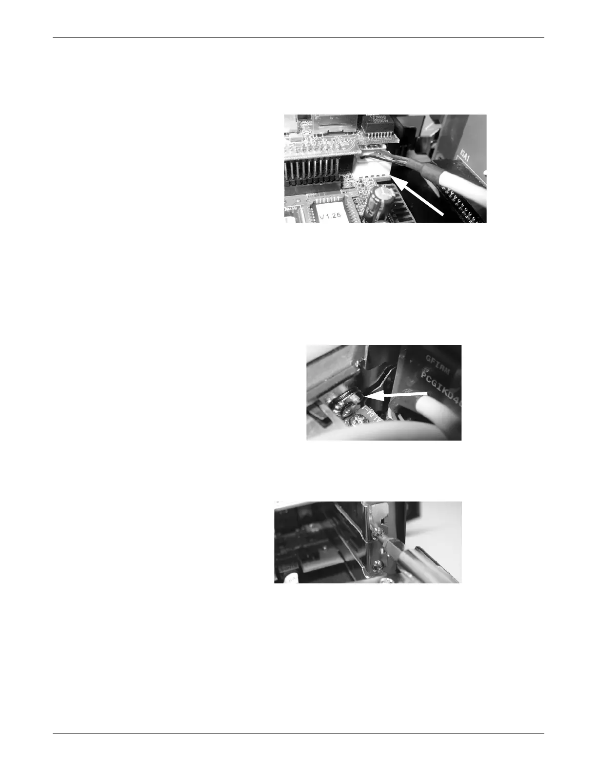
14. Disconnect the external keyboard plug from the receptacle in the back right
corner of the main CPU board. Note the position and orientation of the connector
for reassembly
093A
15. Remove the main CPU board from the chassis.
NOTE
During re-assembly, when inserting the connection tabs into the slots, insert
the end of the middle slot cover in the back panel into the notch at the back
right corner of the main CPU main board as shown in the figure. The slot
cover must fit into the notch in the CPU main board, or the connection tabs
on the main CPU board will not fully seat into the slots.
216A
16. Remove the CPU fan. See CPU fan on page 7-23.
17. Using a phillips screwdriver, remove the screw securing the network card in the
slot.
163A
18. Remove the network card from the slot.