CHAPTER 4: INTERFACES FRONT PANEL INTERFACE
F35 MULTIPLE FEEDER PROTECTION SYSTEM – INSTRUCTION MANUAL 4-49
4
buttons.
4.2.5.2 Standard front panel
After programming LEDs and pushbuttons under Settings > Product Setup > User-Programmable Leds and User-
Programmable Pushbuttons, labels can be created for the front panel.
To create LED and pushbutton labels for a standard front panel:
1. In the EnerVista software, if the F35 is not already listed in the Offline Window area, add it by right-clicking it and
selecting the Add Device to Offline Window option.
2. Click the File > Front Panel Report menu item and select the device.
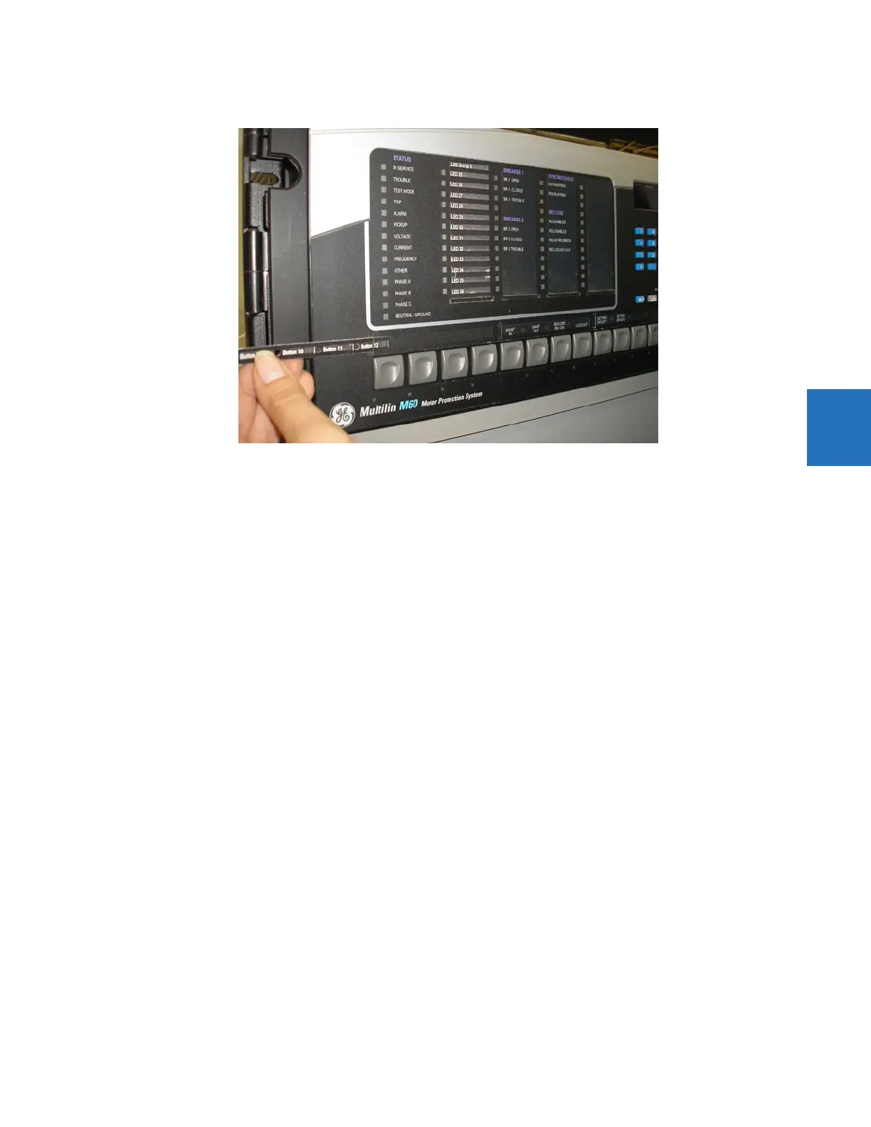
3. In the Front Panel Report window, double-click an LED or pushbutton slot and type a label. If you need to see the
existing front panel remotely, access Actual Values > Front Panel for the online device. If you need to see the In the
figure, note that labelling is being done for the third set of LEDs because the second panel of LEDs was factory-
labelled.