CHAPTER 5: SETTINGS GROUPED ELEMENTS
F35 MULTIPLE FEEDER PROTECTION SYSTEM – INSTRUCTION MANUAL 5-247
5
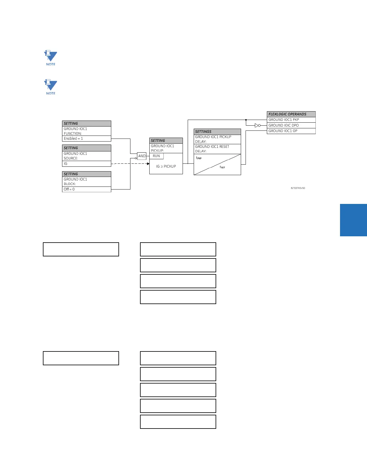
Figure 5-131: Ground IOC1 logic
5.7.7 Negative sequence current
5.7.7.1 Menu
SETTINGS GROUPED ELEMENTS SETTING GROUP 1(6) NEGATIVE SEQUENCE CURRENT
For information on the negative sequence time overcurrent curves, see the Inverse Time Overcurrent Curves section
earlier.
5.7.7.2 Negative sequence time overcurrent (ANSI 51Q, IEC PTOC)
SETTINGS GROUPED ELEMENTS SETTING GROUP 1(6) NEGATIVE SEQUENCE CURRENT NEG SEQ TOC1
These elements measure the current that is connected to the ground channel of a CT/VT module. The conversion
range of a standard channel is from 0.02 to 46 times the CT rating.
This channel can be equipped with a standard or sensitive input. The conversion range of a sensitive channel is
from 0.002 to 4.6 times the CT rating.
NEGATIVE SEQUENCE
CURRENT
NEG SEQ TOC1
See below
NEG SEQ TOC2
NEG SEQ IOC1
See page 5-248
NEG SEQ IOC2
NEG SEQ TOC1
NEG SEQ TOC1
FUNCTION: Disabled
Range: Disabled, Enabled
NEG SEQ TOC1 SIGNAL
SOURCE: SRC 1
Range: SRC 1, SRC 2, SRC 3, SRC 4, SRC 5, SRC 6
NEG SEQ TOC1
PICKUP: 1.000 pu
Range: 0.020 to 30.000 pu in steps of 0.001
NEG SEQ TOC1
CURVE: IEEE Mod Inv
Range: see Overcurrent Curve Types table
NEG SEQ TOC1
TD MULTIPLIER: 1.00
Range: 0.00 to 600.00 in steps of 0.01