CHAPTER 4: INTERFACES FLEXLOGIC DESIGN USING ENGINEER
F35 MULTIPLE FEEDER PROTECTION SYSTEM – INSTRUCTION MANUAL 4-77
4
Figure 4-86: Monitoring a device, with minor error caused by weak battery
4.4.4 View front panel and print labels
This window displays the LEDs that are on the front panel. You can create labels and print them for the device. You do not
use the window to add text labels and upload them to the device. Custom labelling is also outlined earlier in this chapter;
see the Front Panel Labelling section.
To view the front panel:
1. In the Offline Window area of the software, expand the Engineer entry for the device.
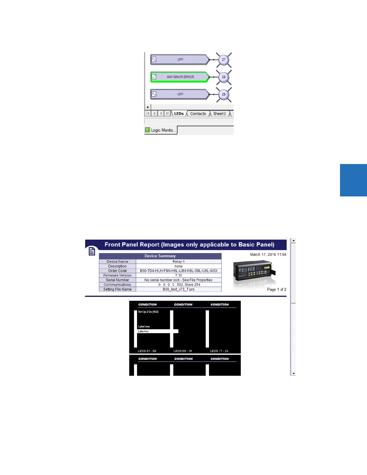
2. Double-click the Front Panel Report entry. The report displays. The Device Summary is read from the settings file and
cannot be changed. The LEDs and pushbuttons display below the summary.
3. To save the report, click File > Save As, enter a file name, and select the front panel report (FPR), JPG, or PDF format.
Figure 4-87: Front panel display in Engineer
To print labels:
1. In the Front Panel Report window, double-click an LED or pushbutton and enter text.
2. To print the labels, click the Print icon on the toolbar.
3. To save the report and labels, click File > Save As, enter a file name, and select the FPR, JPG, or PDF format.
4. Use the instructions in the second tab of the window to add the labels to the physical device.