CHAPTER 4: INTERFACES FRONT PANEL INTERFACE
F35 MULTIPLE FEEDER PROTECTION SYSTEM – INSTRUCTION MANUAL 4-59
4
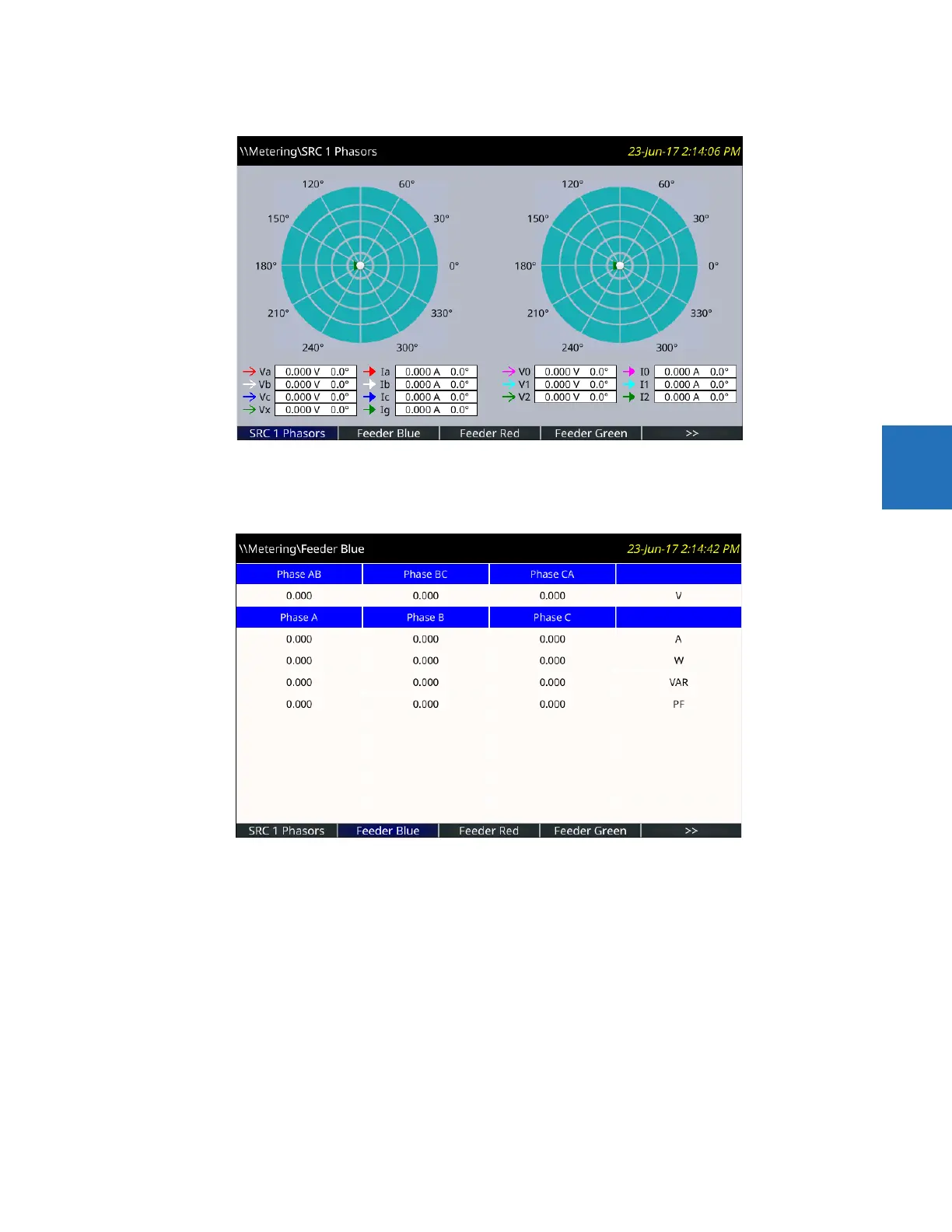
Figure 4-62: Phasor display
The configurable name displays in the header and Tab pushbutton label. Factory default names are Page 1, Page 2, and so
on.
Figure 4-63: Metered actual values
The pages are configured in the software under Settings > Product Setup > Graphical Panel > Metering Editor.
4.2.9 Breaker control
The F35 can interface with associated circuit breakers. In many cases the application monitors the state of the breaker,
that can be presented on front panel LEDs, along with a breaker trouble indication. Breaker operations can be manually
initiated from the front panel keypad or automatically initiated from a FlexLogic operand. A setting is provided to assign
names to each breaker; this user-assigned name is for the display of related flash messages. These features are provided
for two breakers; the user can use only those portions of the design relevant to a single breaker, which must be breaker 1.
It is assumed in the following discussion that the
SETTINGS SYSTEM SETUP BREAKERS BREAKER 1(2) BREAKER
FUNCTION
setting is "Enabled" for each breaker.