F35 MULTIPLE FEEDER PROTECTION SYSTEM – INSTRUCTION MANUAL 10-1
F35 Multiple Feeder Protection System
Chapter 10: Maintenance
Maintena nce
This chapter outlines monitoring, maintenance, repair, storage, and disposal of the hardware and software.
10.1 Monitoring
Devices and data can be monitored.
10.1.1 Devices with Site Targets
To view an overview of devices:
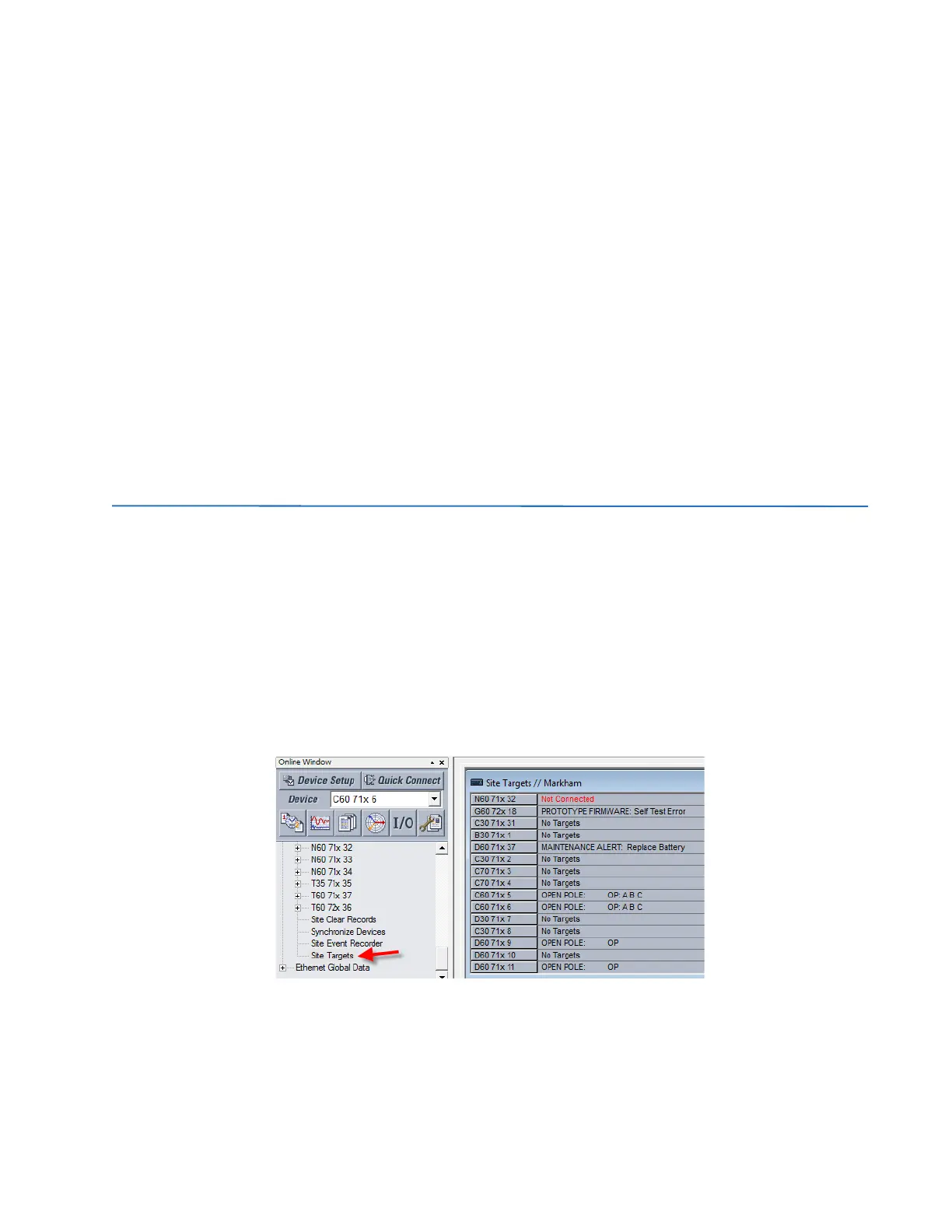
1. Access the Site Targets item in the Online Window area, below the list of devices. It can take a few minutes for all
devices to be read.
2. Acknowledge any messages for unaccessible devices. The Site Targets window opens when done.
Figure 10-1: Site Targets window
10.1.2 Data with Modbus Analyzer
Use the Modbus Analyzer under Maintenance > Modbus Analyzer to monitor the values of the UR device. Use the Modbus
memory map addresses outlined in the UR Family Communications Guide for the entries.
The upper part of the window displays values. The lower part of the window is for factory service use.