6-4 F35 MULTIPLE FEEDER PROTECTION SYSTEM – INSTRUCTION MANUAL
STATUS CHAPTER 6: ACTUAL VALUES
6
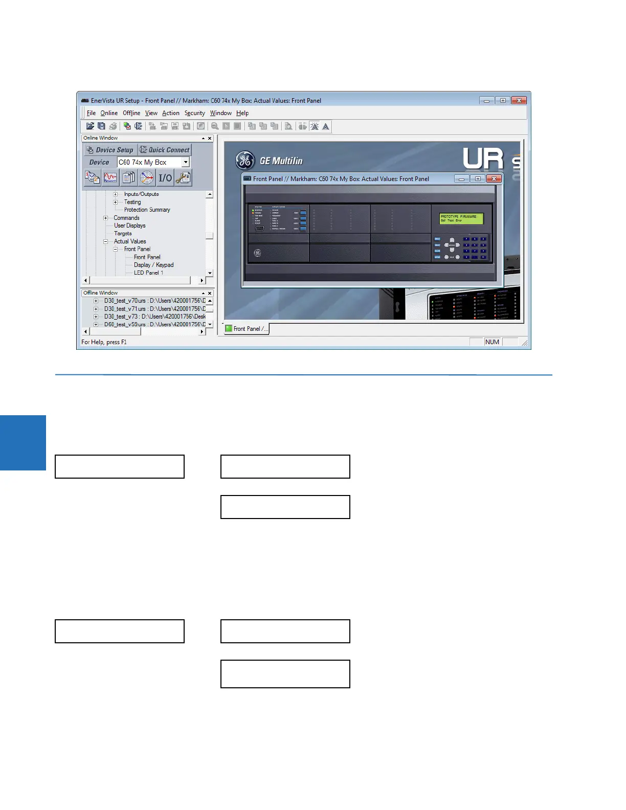
Figure 6-1: Front panel use in the software (C60 shown)
6.3 Status
6.3.1 Contact inputs
ACTUAL VALUES STATUS CONTACT INPUTS
The present status of the contact inputs is shown here. The first line of a message display indicates the ID of the contact
input. For example, ‘Cont Ip 1’ refers to the contact input in terms of the default name-array index. The second line of the
display indicates the logic state of the contact input.
6.3.2 Virtual inputs
ACTUAL VALUES STATUS VIRTUAL INPUTS
The present status of the 64 virtual inputs is shown here. The first line of a message display indicates the ID of the virtual
input. For example, ‘Virt Ip 1’ refers to the virtual input in terms of the default name. The second line of the display indicates
the logic state of the virtual input.
CONTACT INPUTS
Cont Ip 1
Off
Range: On, Off
Cont Ip xx
Off
Range: On, Off
VIRTUAL INPUTS
Virt Ip 1
Off
Range: On, Off
Virt Ip 64
Off
Range: On, Off