CHAPTER 3: INSTALLATION DIRECT INPUT AND OUTPUT COMMUNICATIONS
F35 MULTIPLE FEEDER PROTECTION SYSTEM – INSTRUCTION MANUAL 3-33
3
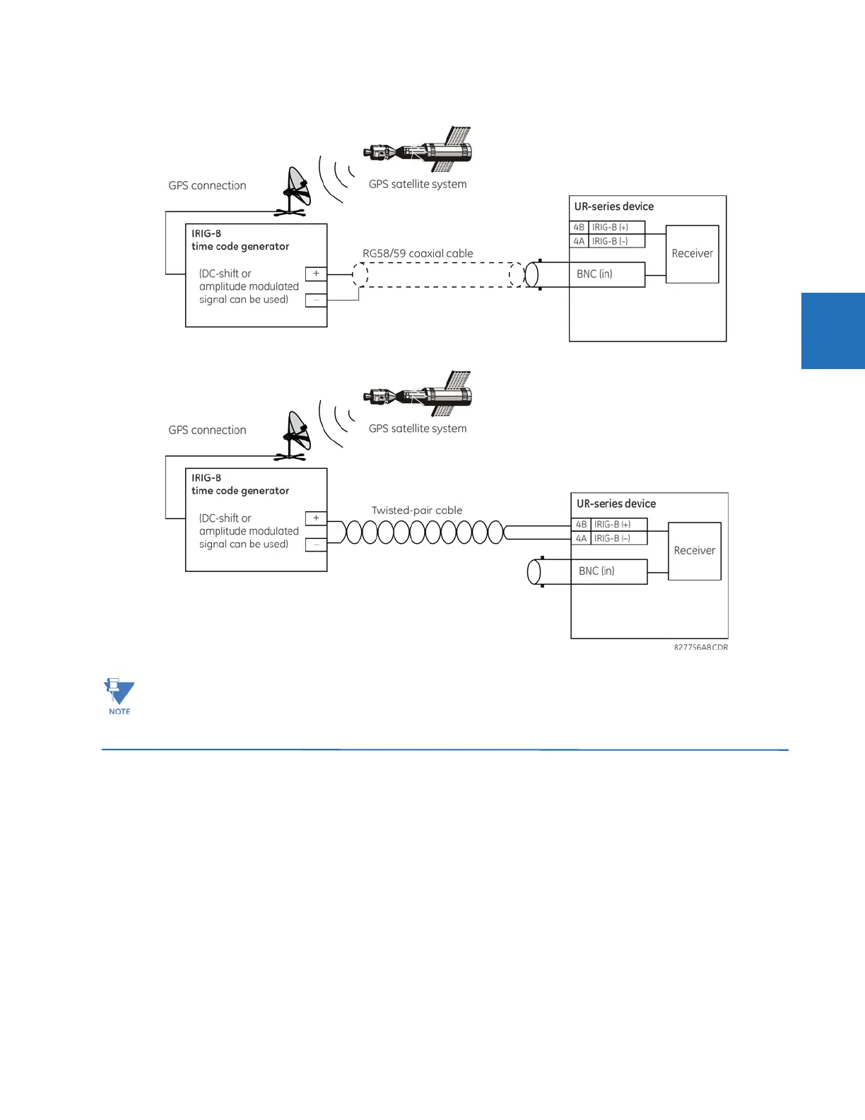
Figure 3-30: Options for the IRIG-B connection
3.4 Direct input and output communications
3.4.1 Description
The direct inputs and outputs feature makes use of the type 7 series of communications modules and allows direct
messaging between UR devices. The communications modules are outlined in the table later in this section.
The communications channels are normally connected in a ring configuration, as shown in the following figure. The
transmitter of one module is connected to the receiver of the next module. The transmitter of this second module is then
connected to the receiver of the next module in the ring. This is continued to form a communications ring. The figure
illustrates a ring of four UR-series relays with the following connections: UR1-Tx to UR2-Rx, UR2-Tx to UR3-Rx, UR3-Tx to
UR4-Rx, and UR4-Tx to UR1-Rx. A maximum of 16 URs can be connected in a single ring.
Using an amplitude-modulated receiver causes errors up to 1 ms in event time stamping.