3-52 F35 MULTIPLE FEEDER PROTECTION SYSTEM – INSTRUCTION MANUAL
INSTALL SOFTWARE CHAPTER 3: INSTALLATION
3
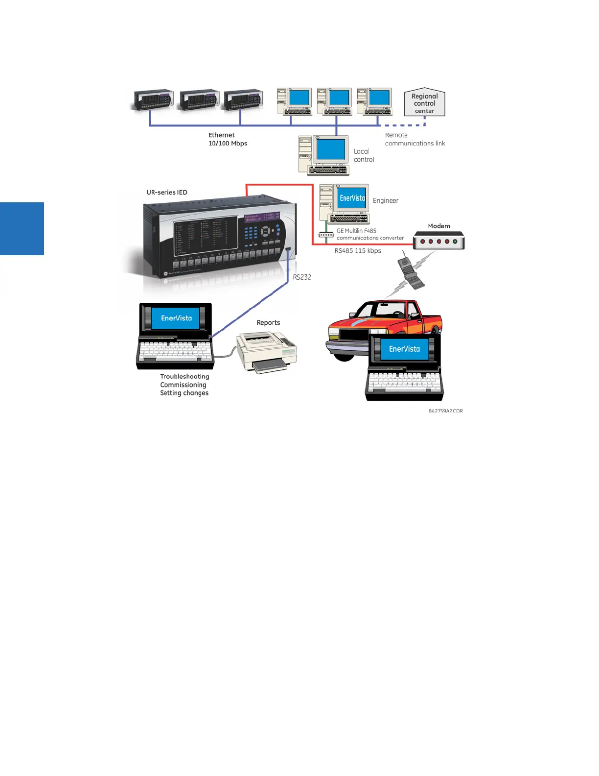
Figure 3-58: Relay communication options
To communicate through the F35 rear RS485 port from a computer RS232 port, the GE Grid Solutions RS232/RS485
converter box is required. This device (catalog number F485) connects to the computer using a straight-through serial
cable. A shielded twisted-pair (20, 22, or 24 AWG) connects the F485 converter to the F35 rear communications port. The
converter terminals (+, –, GND) are connected to the F35 communication module (+, –, COM) terminals. See the CPU
Communication Ports section in chapter 3 for details. The line is terminated with an R-C network (that is, 120 Ω, 1 nF) as
described in this chapter.
3.6.2 System requirements
The relay front panel or the EnerVista UR Setup software can be used to communicate with the relay. The software
interface is the preferred method to edit settings and view actual values because the computer monitor can display more
information.
The minimum system requirements for the EnerVista software are as follows:
• Intel Pentium processor (dual core)
• Microsoft Windows 7 with Service Pack 1 (32-bit or 64-bit) or Windows Server 2008 Release 2 with Service Pack 1 (64-
bit)
• 1 GB free hard drive space
•2 GB RAM
• 1280 x 800 display screen