CHAPTER 5: SETTINGS CONTROL ELEMENTS
F35 MULTIPLE FEEDER PROTECTION SYSTEM – INSTRUCTION MANUAL 5-281
5
5.8.10 Monitoring elements
5.8.10.1 Menu
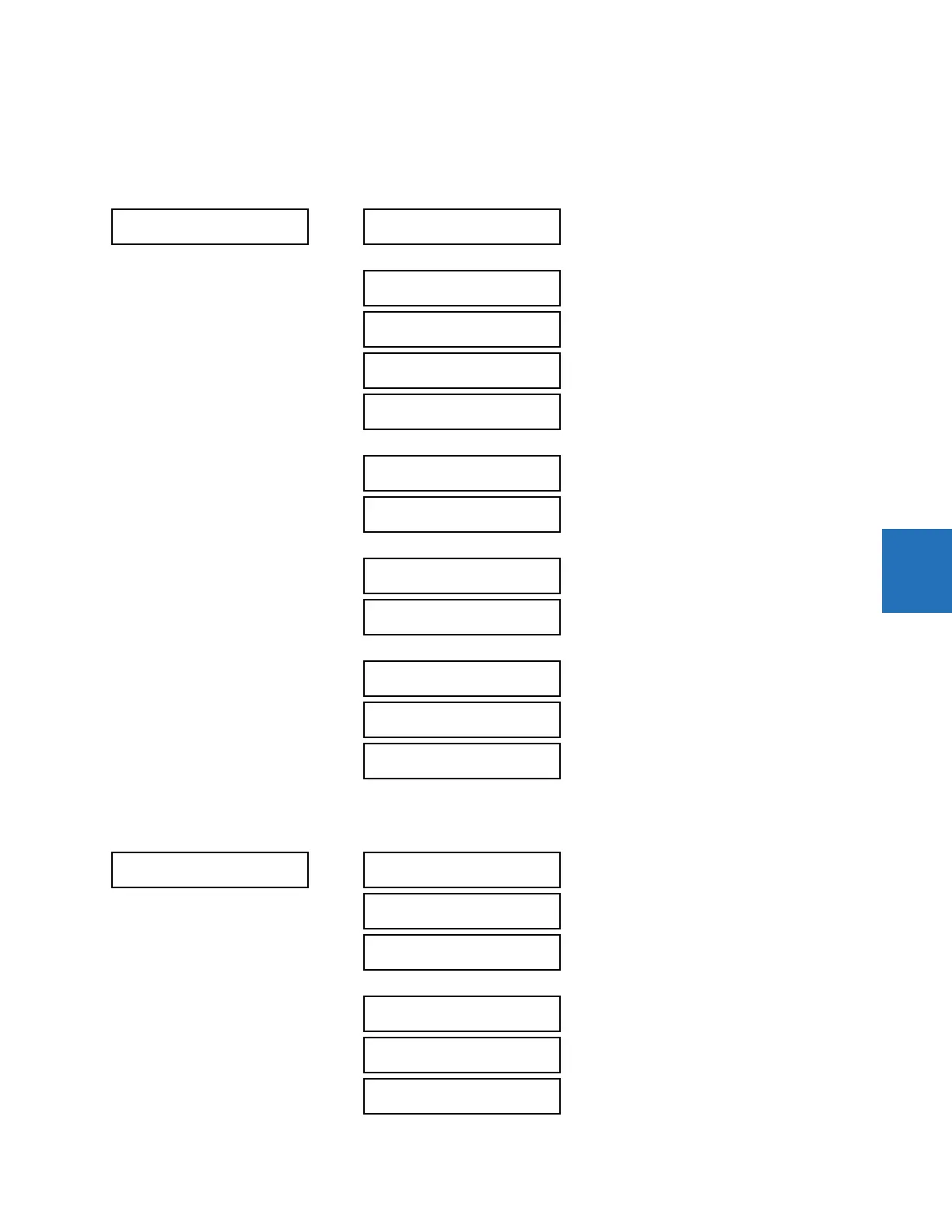
SETTINGS CONTROL ELEMENTS MONITORING ELEMENTS
5.8.10.2 Breaker arcing current
SETTINGS CONTROL ELEMENTS MONITORING ELEMENTS BREAKER 1(6) ARCING CURRENT
MONITORING
ELEMENTS
BREAKER 1
ARCING CURRENT
See below
BREAKER 6
ARCING CURRENT
BREAKER
FLASHOVER 1
See page 5-288
BREAKER
FLASHOVER 2
BREAKER RESTRIKE 1
See page 5-293
BREAKER RESTRIKE 3
INCIPIENT FAULT 1
See page 5-295
INCIPIENT FAULT 6
VT FUSE FAILURE 1
See page 5-297
VT FUSE FAILURE 6
THERMAL OVERLOAD
PROTECTION
See page 5-299
BROKEN CONDUCTOR
See page 5-302
BREAKER 1
ARCING CURRENT
BKR 1 ARC AMP
FUNCTION: Disabled
Range: Disabled, Enabled
BKR 1 ARC AMP
SOURCE: SRC 1
Range: SRC 1, SRC 2, SRC 3, SRC 4, SRC 5, SRC 6
BKR 1 ARC AMP INT-A:
Off
Range: FlexLogic operand
BKR 1 ARC AMP INT-C:
Off
Range: FlexLogic operand
BKR 1 ARC AMP
DELAY: 0.000 s
Range: 0.000 to 65.535 s in steps of 0.001
BKR 1 ARC AMP LIMIT:
1000 kA2-cyc
Range: 0 to 50000 kA
2
-cycle in steps of 1