5-280 F35 MULTIPLE FEEDER PROTECTION SYSTEM – INSTRUCTION MANUAL
CONTROL ELEMENTS CHAPTER 5: SETTINGS
5
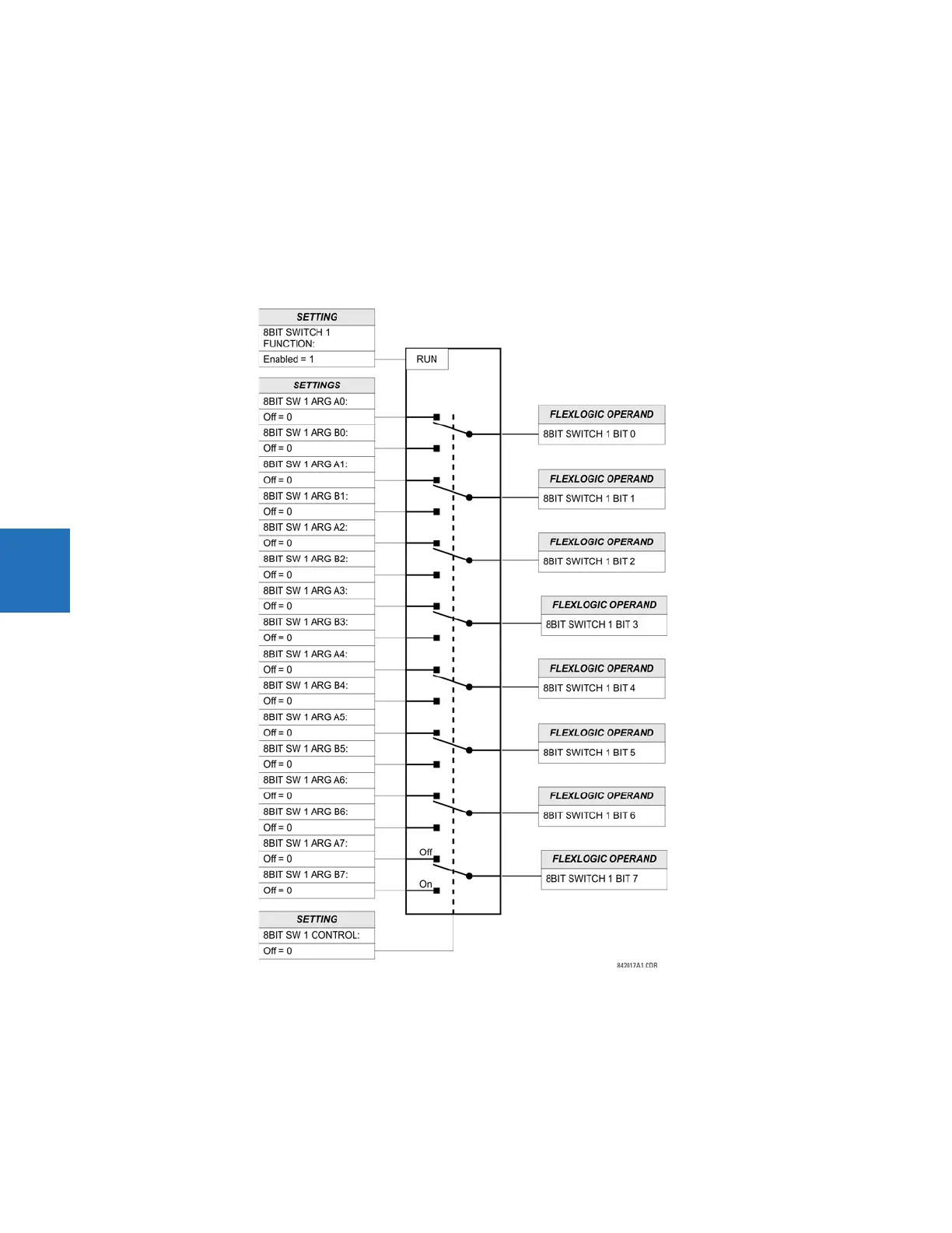
The switch runs every half power cycle (every four protection passes).
8BIT SW 1 ARG A0 to 8BIT SW 1 ARG A7 — These settings specify FlexLogic operands that constitute the first (A) input of the
switch. These operands are routed to the output operands if the control input is in the "Off" position.
BIT SW 1 ARG B0 to 8BIT SW 1 ARG B7 — These settings specify FlexLogic operands that constitute the second (B) input of the
switch. These operands are routed to the output operands if the control input is in the "On" position.
8BIT SW 1 CONTROL — This setting specifies FlexLogic operands to control the routing between the A and B inputs of the
switch. If the control operand is in the "Off" state, the first (A) input is switched to the output. If the control operand is in the
"On" state, the second (B) input is switched to the output. The switching takes place instantaneously.
Figure 5-154: 8-bit switch logic