6-22 F35 MULTIPLE FEEDER PROTECTION SYSTEM – INSTRUCTION MANUAL
METERING CHAPTER 6: ACTUAL VALUES
6
6.4.3 Tracking frequency
ACTUAL VALUES METERING TRACKING FREQUENCY
The tracking frequency displays here. The frequency is tracked based on the selection of the reference source with the
FREQUENCY AND PHASE REFERENCE setting in the SETTINGS SYSTEM SETUP POWER SYSTEM menu. See the Power
System section of chapter 5 for details.
6.4.4 FlexElements
ACTUAL VALUES METERING FLEXELEMENTS FLEXELEMENT 1(16)
The operating signals for the FlexElements are displayed in pu values using the following definitions of the base units.
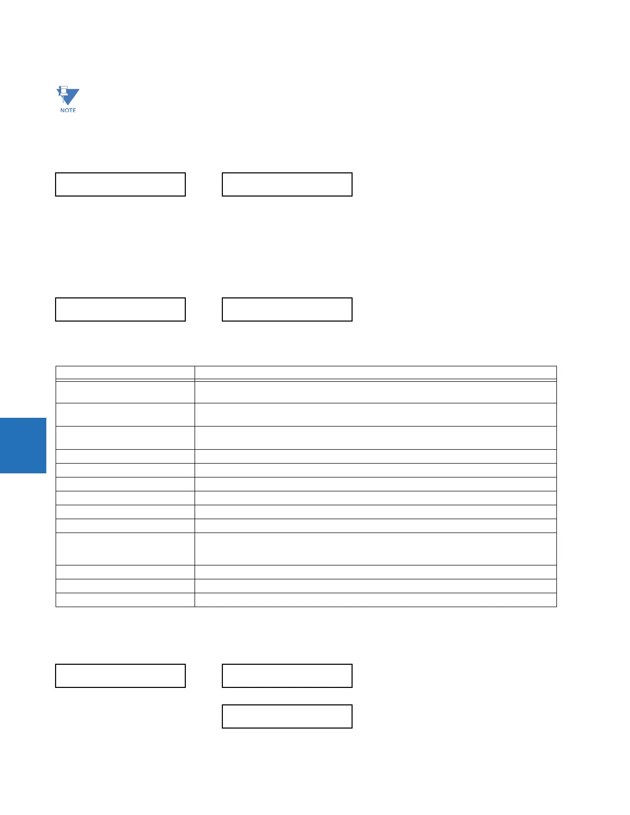
Table 6-2: FlexElement base units
6.4.5 RxGOOSE analogs
ACTUAL VALUES METERING RxGOOSE Analogs
Voltage harmonics are calculated only for Wye connected phase VTs. Ensure that the
SYSTEM SETUP AC INPUTS
VOLTAGE BANK F5 PHASE VT XX CONNECTION
setting is “Wye” to enable voltage harmonics metering.
TRACKING FREQUENCY
TRACKING FREQUENCY:
60.00 Hz
FLEXELEMENT 1
FLEXELEMENT 1
OpSig: 0.000
Base unit Description
BREAKER ACC ARCING AMPS
(Brk X Acc Arc Amp A, B, and C)
BASE = 2000 kA
2
× cycle
BREAKER ARCING AMPS
(Brk X Arc Amp A, B, and C)
BASE = 1 kA
2
× cycle
DCmA BASE = maximum value of the DCMA INPUT MAX setting for the two transducers configured
under the +IN and –IN inputs.
FAULT LOCATION BASE = Line Length as specified in Fault Report
FREQUENCY f
BASE
= 1 Hz
PHASE ANGLE ϕ
BASE
= 360 degrees (see the UR angle referencing convention)
POWER FACTOR PF
BASE
= 1.00
RTDs BASE = 100°C
SOURCE CURRENT I
BASE
= maximum nominal primary RMS value of the +IN and –IN inputs
SOURCE ENERGY
(Positive and Negative Watthours,
Positive and Negative Varhours)
E
BASE
= 10000 MWh or MVAh, respectively
SOURCE POWER P
BASE
= maximum value of V
BASE
× I
BASE
for the +IN and –IN inputs
SOURCE THD & HARMONICS BASE = 1%
SOURCE VOLTAGE V
BASE
= maximum nominal primary RMS value of the +IN and –IN inputs
RxGOOSE
Analogs
RxGOOSE Analog 1
0.000
RxGOOSE Analog 32
0.000