6-16 F35 MULTIPLE FEEDER PROTECTION SYSTEM – INSTRUCTION MANUAL
METERING CHAPTER 6: ACTUAL VALUES
6
6.4.2 Sources
6.4.2.1 Menu
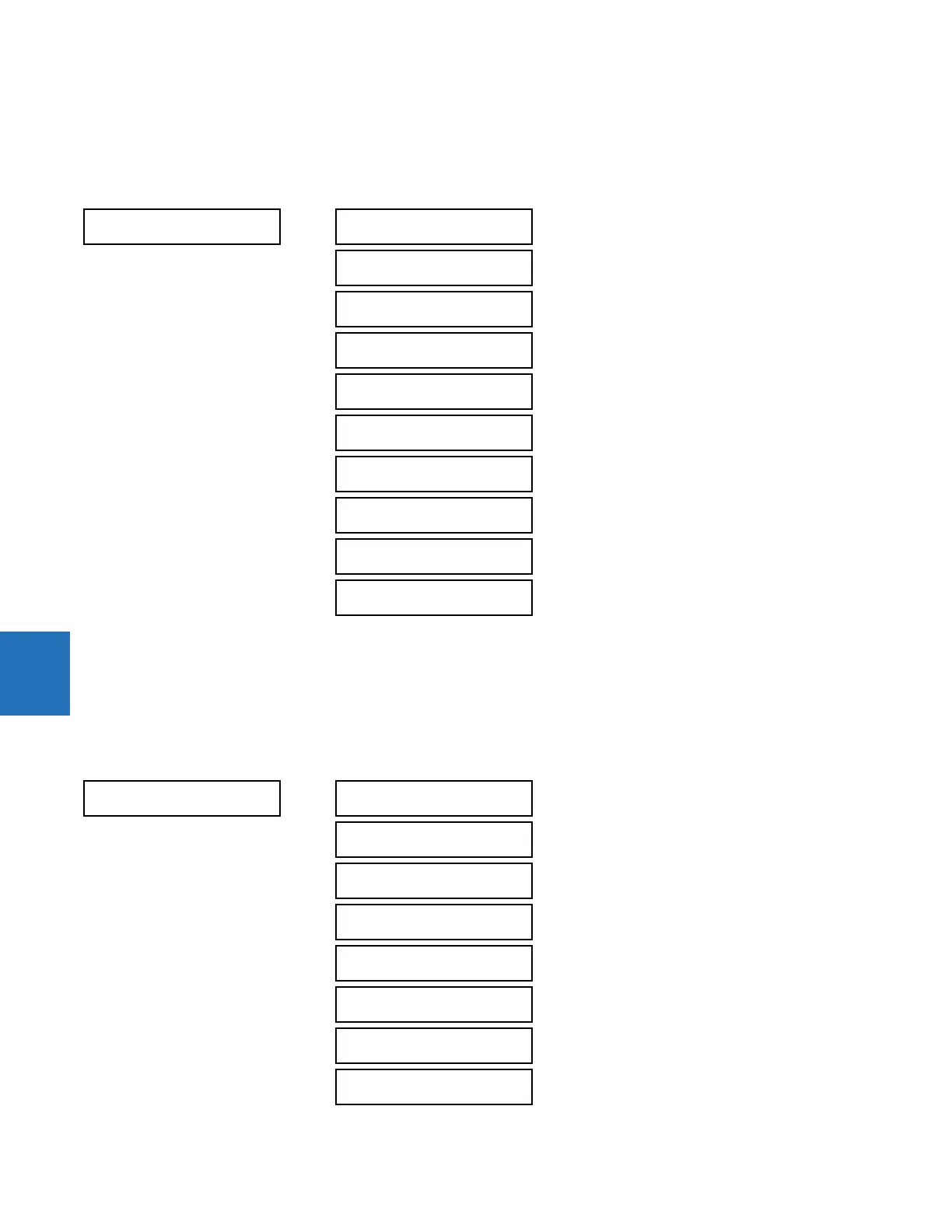
ACTUAL VALUES METERING SOURCE SRC 1
This menu displays the metered values available for each source.
Metered values presented for each source depend on the phase and auxiliary VTs and phase and ground CTs assignments
for this particular source. For example, if no phase VT is assigned to this source, then any voltage, energy, and power
values are unavailable.
6.4.2.2 Phase current metering
ACTUAL VALUES METERING SOURCE SRC 1 PHASE CURRENT
SOURCE SRC 1
PHASE CURRENT
SRC 1
See below
GROUND CURRENT
SRC 1
See page 6-17
PHASE VOLTAGE
SRC 1
See page 6-17
AUXILIARY VOLTAGE
SRC 1
See page 6-18
POWER
SRC 1
See page 6-18
ENERGY
SRC 1
See page 6-19
DEMAND
SRC 1
See page 6-19
FREQUENCY
SRC 1
See page 6-20
CURRENT HARMONICS
SRC 1
See page 6-21
VOLTAGE HARMONICS
SRC 1
See page 6-21
PHASE CURRENT
SRC 1
SRC 1 RMS Ia: 0.000
b: 0.000 c: 0.000 A
SRC 1 RMS Ia:
0.000 A
SRC 1 RMS Ib:
0.000 A
SRC 1 RMS Ic:
0.000 A
SRC 1 RMS In:
0.000 A
SRC 1 PHASOR Ia:
0.000 A 0.0°
SRC 1 PHASOR Ib:
0.000 A 0.0°
SRC 1 PHASOR Ic:
0.000 A 0.0°