CHAPTER 5: SETTINGS CONTROL ELEMENTS
F35 MULTIPLE FEEDER PROTECTION SYSTEM – INSTRUCTION MANUAL 5-297
5
INCIPIENT FAULT 1 SOURCE — Selects a current source for the incipient cable fault detector element. This source must be
assigned a valid CT bank.
INCIPIENT FAULT 1 PICKUP — Specifies the pickup level of the overcurrent detector in per-unit values of the CT nominal
current.
INCIPNT FLT 1 MODE — There are two modes of operation available for the incipient cable fault detector element. In the
“Number of counts” mode, a trip is initiated only after the selected number of faults is detected. In the “Counts per window”
mode, a trip is initiated only after the selected number of faults is detected within the time specified by the
INCIPNT FLT 1
DETECT WINDOW
setting.
INCIPIENT FLT 1 TRIP COUNTS NUMBER — Selects the number of faults required to initiate a trip.
INCIPNT FLT 1 DETECT WINDOW — Specifies a time window for “Counts per window” mode of operation.
INCIPIENT FAULT 1 RESET DELAY — Specifies a reset time for the output after the trip is initiated.
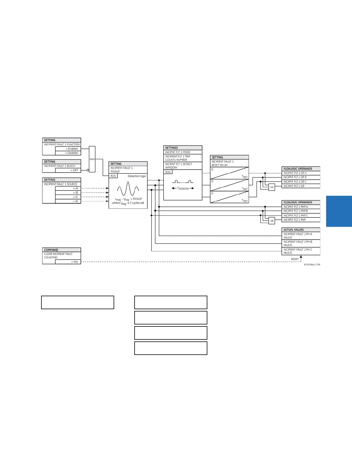
Figure 5-164: Incipient cable fault detector logic
5.8.10.5 VT fuse failure
SETTINGS CONTROL ELEMENTS MONITORING ELEMENTS VT FUSE FAILURE 1(6)
Every signal source includes a fuse failure scheme.
The VT fuse failure detector is used to raise an alarm and/or block elements that operate incorrectly for a full or partial loss
of AC potential caused by one or more blown fuses. Some elements that can be blocked (via the BLOCK input) are distance,
voltage restrained overcurrent, and directional current.
There are two classes of fuse failure that occur:
• Class A — Loss of one or two phases
• Class B — Loss of all three phases
VT FUSE FAILURE 1
VT FUSE FAILURE 1
FUNCTION: Disabled
Range: Disabled, Enabled
VT FUSE FAILURE 1
ALARM DELAY: 1.000 s
Range: 0.000 to 65.535 s in steps of 0.001
NEUTRAL WIRE OPEN 1
DETECTION: Disabled
Range: Disabled, Enabled
NEUTRAL WIRE OPEN 1
3 HARM PKP: 0.100 pu
Range: 0.004 to 3.000 pu in steps of 0.001