5-298 F35 MULTIPLE FEEDER PROTECTION SYSTEM – INSTRUCTION MANUAL
CONTROL ELEMENTS CHAPTER 5: SETTINGS
5
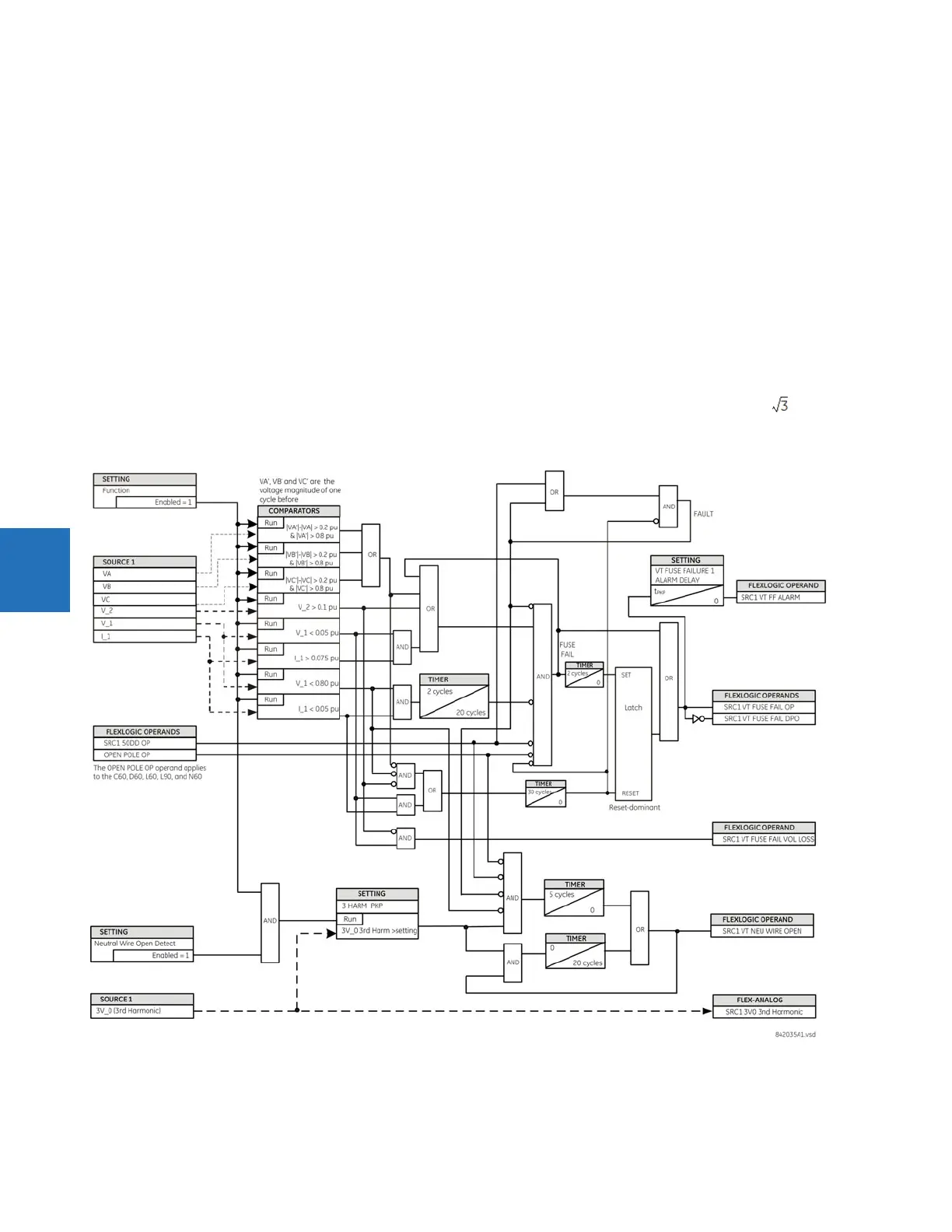
Different means of detection are required for each class. An indication of class A failures is a significant level of negative-
sequence voltage, whereas an indication of class B failures is when positive sequence current is present and there is an
insignificant amount of positive sequence voltage. Also, a rapid decrease in the phase voltages magnitude from a healthy
voltage level without disturbance in current can indicate VT fuse fail conditions. These noted indications of fuse failure can
also be present when faults are present on the system, so a means of detecting faults and inhibiting fuse failure
declarations during these events is provided.
Once the fuse failure condition is declared, it is sealed-in until the cause that generated it disappears.
An additional condition is introduced to inhibit a fuse failure declaration when the monitored circuit is de-energized;
positive-sequence voltage and current are both below threshold levels.
VT FUSE FAILURE 1 FUNCTION — Enables and disables the fuse failure feature for Source 1 VT Fuse Fail.
NEUTRAL WIRE OPEN 1 DETECTION — Enables and disables the VT neutral wire open detection function. When the VT is
connected in Delta, do not enable this function because there is no neutral wire for Delta connected VT.
NEUTRAL WIRE OPEN 1 3 HRAM PKP — Specifies the pickup level of 3rd harmonic of 3V0 signal for the NEUTRAL WIRE OPEN
DETECTION
logic to pick up.
Base voltage for this element is
PHASE VT SECONDARY setting in the case of WYE VTs and (PHASE VT SECONDARY)/ in case
of DELTA VTs. The setting is found under
SETTINGS SYSTEM SETUP AC INPUTS VOLTAGE BANK PHASE VT SECONDARY.
Figure 5-165: VT fuse fail logic