5-296 F35 MULTIPLE FEEDER PROTECTION SYSTEM – INSTRUCTION MANUAL
CONTROL ELEMENTS CHAPTER 5: SETTINGS
5
There are two incipient cable fault detection elements for each CT/VT module in the relay.
Before a permanent cable fault occurs, there are usually signs of degrading insulation manifesting itself as a short, mostly
half-cycle spikes asserting at the phase voltage peak. Due to shortness of such spikes, they are not usually detected by the
instantaneous protection of the feeder, which operates on the RMS or fundamental component of the phase current with a
relatively high pickup.
The number of detected incipient faults in each phase is counted and available in the
ACTUAL VALUES STATUS
INCIPIENT FAULT
menus. The counters can be reset with the COMMANDS CLEAR RECORDS CLEAR INCIPENT FAULT
COUNTERS
command.
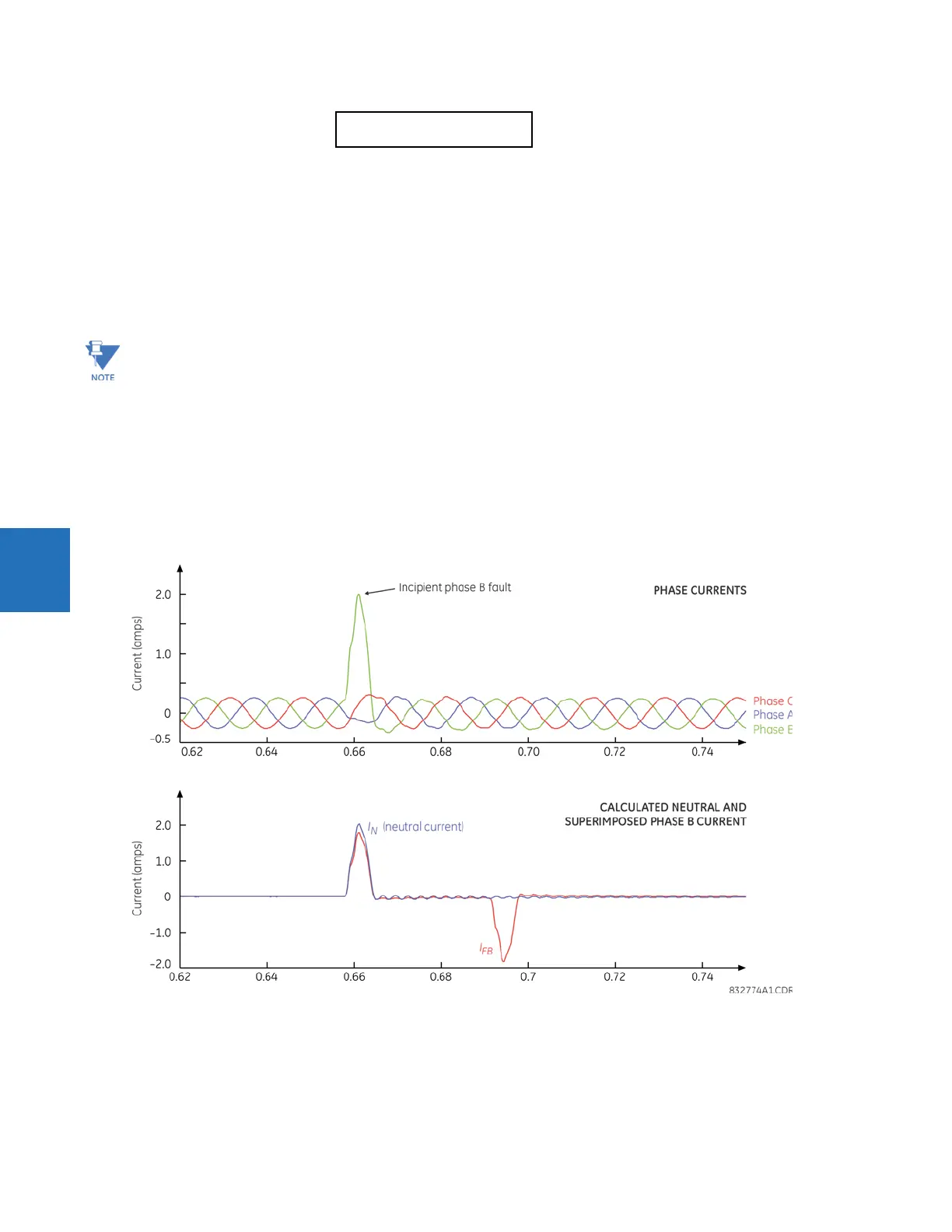
The figure illustrates a recorded field case of an incipient phase B fault. The top portion of the figure shows the raw A, B,
and C currents. The bottom portion shows the neutral current (blue) and reveals the fault period from under the load and
the superimposed phase B current (red). The superimposed current shows two fault current blips as the data slides through
the two-cycle memory window. During the actual fault, the neutral current and the superimposed phase B currents closely
correspond, confirming the incipient fault hypothesis and identifying the affected phase.
Figure 5-163: Illustration of the incipient fault detector algorithm
The following settings are available for each incipient cable fault detector.
INCIPIENT FAULT 1 FUNCTION — This setting enables and disables operation of the incipient fault detection element.
INCIPNT FLT 1 BLOCK — Blocks operation of the incipient cable fault detector element. Assertion of the FlexLogic operand
assigned to this setting blocks operation.
INCIPIENT FAULT 1
EVENTS: Disabled
Range: Disabled, Enabled
Changes to any of the incipient cable fault detector settings resets of the number of the incipient faults detected to
zero.
To provide a clear timing indication when the incipient fault occurred, the incipient fault event is time-stamped with
the time the fault actually occurred. However, the FlexLogic operand is asserted four cycles later, when the incipient
fault pattern is confirmed and therefore detected.