CHAPTER 5: SETTINGS PRODUCT SETUP
F35 MULTIPLE FEEDER PROTECTION SYSTEM – INSTRUCTION MANUAL 5-53
5
The Distributed Network Protocol (DNP) allows for the optimization of control and data acquisition between the equipment
in the substation and the central control center. The protocol is scalable; that is, it is designed to be compatible with the
latest high speed LAN technology yet still be implemented over slower speed serial links.
The DNP improves upon many master-slave protocols by improving overall communication performance requirements
and provides time-stamping with millisecond accuracy.
The F35 supports the Distributed Network Protocol (DNP) version 3.0. DNP is enabled when the
SETTINGS PRODUCT SETUP
COMMUNICATIONS PROTOCOL
setting is set to DNP 3.0. The F35 can be used as a DNP slave device connected to
multiple DNP masters (usually an RTU or a SCADA master station). Since the F35 maintains two sets of DNP data change
buffers and connection information, two DNP masters can actively communicate with the F35 at one time.
DNP is not available using the USB port on the graphical front panel.
See the UR Family Communications Guide for more information on DNP.
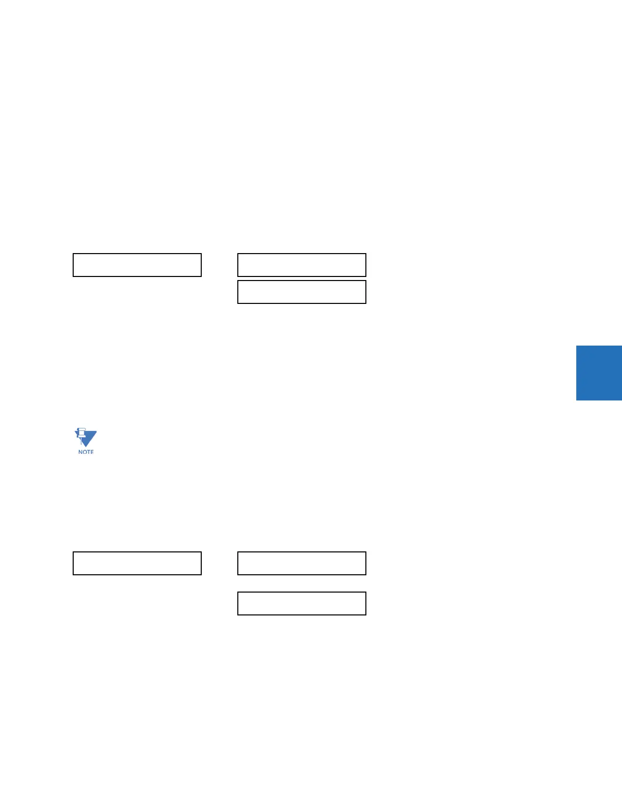
The DNP Channels sub-menu is shown.
SETTINGS PRODUCT SETUP COMMUNICATIONS DNP PROTOCOL DNP CHANNELS
The
DNP CHANNEL 1 PORT and DNP CHANNEL 2 PORT settings select the communications port assigned to the DNP protocol
for each channel. Once DNP is assigned to a serial port, DNP is the only protocol running on that port; Modbus or IEC
60870-5-103 are disabled. If DNP is assigned to RS485, the protocol must be set to DNP on the serial port configuration as
well, for the change to take effect. When the
DNP CHANNEL 1(2) PORT setting is set to “Network - TCP,” the channel 1(2) DNP
protocol can be used over TCP/IP on the Ethernet ports. When this value is set to “Network - UDP,” the DNP protocol can be
used over UDP/IP on channel 1 only. The "Front Panel - RS232" setting does not apply to the graphical front panel; when
selected the DNP client cannot establish a connection on a USB port.
For any change to take effect, restart the relay.
The
DNP ADDRESS setting is the DNP slave address. This number identifies the F35 on a DNP communications link. Assign a
unique address to each DNP slave.
The F35 can specify a maximum of five clients for its DNP connections. These are IP addresses for the controllers to which
the F35 can connect. The settings follow.
SETTINGS PRODUCT SETUP COMMUNICATIONS DNP PROTOCOL DNP NETWORK CLIENT ADDRESSES
The
DNP TCP/UDP PORT NUMBER setting is for normal DNP operation. To close the port, set the port number to 0. The change
takes effect when the F35 is restarted.
The
DNP UNSOL RESPONSE FUNCTION is set to “Disabled” for RS485 applications since there is no collision avoidance
mechanism. The DNP UNSOL RESPONSE TIMEOUT sets the time the F35 waits for a DNP master to confirm an unsolicited
response. The
DNP UNSOL RESPONSE MAX RETRIES setting determines the number of times the F35 retransmits an
unsolicited response without receiving confirmation from the master; a value of “255” allows infinite re-tries. The
DNP
UNSOL RESPONSE DEST ADDRESS
is the DNP address to which all unsolicited responses are sent. The IP address to which
solicited responses are sent is determined by the F35 from the current TCP connection or the most recent UDP message.
DNP CHANNELS
DNP CHANNEL 1 PORT:
NONE
Range: NONE, COM1 - RS485, COM2 - RS485, FRONT
PANEL - RS232, NETWORK - TCP, NETWORK - UDP
DNP CHANNEL 2 PORT:
NONE
Range: NONE, COM1 - RS485, COM2 - RS485, FRONT
PANEL - RS232, NETWORK - TCP
Do not set more than one protocol to the same TCP/UDP port number, as this results in unreliable operation of
those protocols.
DNP NETWORK
CLIENT ADDRESSES
CLIENT ADDRESS 1:
0.0.0.0
Range: standard IP address
CLIENT ADDRESS 5:
0.0.0.0
Range: standard IP address