5-252 F35 MULTIPLE FEEDER PROTECTION SYSTEM – INSTRUCTION MANUAL
GROUPED ELEMENTS CHAPTER 5: SETTINGS
5
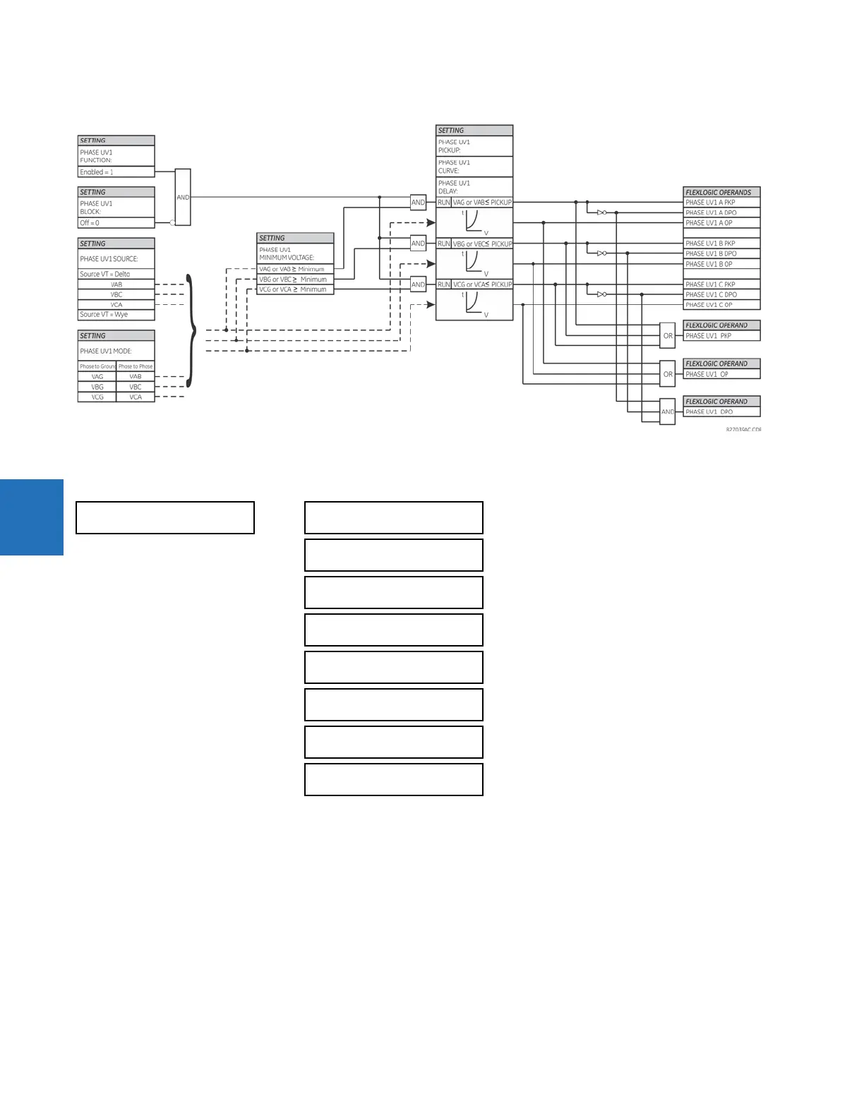
Figure 5-135: Phase undervoltage1 logic
5.7.8.3 Phase overvoltage (ANSI 59P, IEC PTOV)
SETTINGS GROUPED ELEMENTS SETTING GROUP 1(6) VOLTAGE ELEMENTS PHASE OVERVOLTAGE1
There are three phase overvoltage elements available. A phase overvoltage element is used as an instantaneous element
with no intentional time delay or as a definite time element. The input voltage is the phase-to-phase voltage, either
measured directly from delta-connected VTs or as calculated from phase-to-ground (wye) connected VTs. The figure
shows specific voltages to be used for each phase.
PHASE
OVERVOLTAGE1
PHASE OV1
FUNCTION: Disabled
Range: Disabled, Enabled
PHASE OV1 SIGNAL
SOURCE: SRC 1
Range: SRC 1, SRC 2, SRC 3, SRC 4, SRC 5, SRC 6
PHASE OV1
PICKUP: 1.000 pu
Range: 0.004 to 3.000 pu in steps of 0.001
PHASE OV1 PICKUP
DELAY: 1.00 s
Range: 0.00 to 600.00 s in steps of 0.01
PHASE OV1 RESET
DELAY: 1.00 s
Range: 0.00 to 600.00 s in steps of 0.01
PHASE OV1 BLOCK:
Off
Range: FlexLogic Operand
PHASE OV1
TARGET: Self-reset
Range: Self-reset, Latched, Disabled
PHASE OV1
EVENTS: Disabled
Range: Disabled, Enabled