CHAPTER 5: SETTINGS CONTROL ELEMENTS
F35 MULTIPLE FEEDER PROTECTION SYSTEM – INSTRUCTION MANUAL 5-275
5
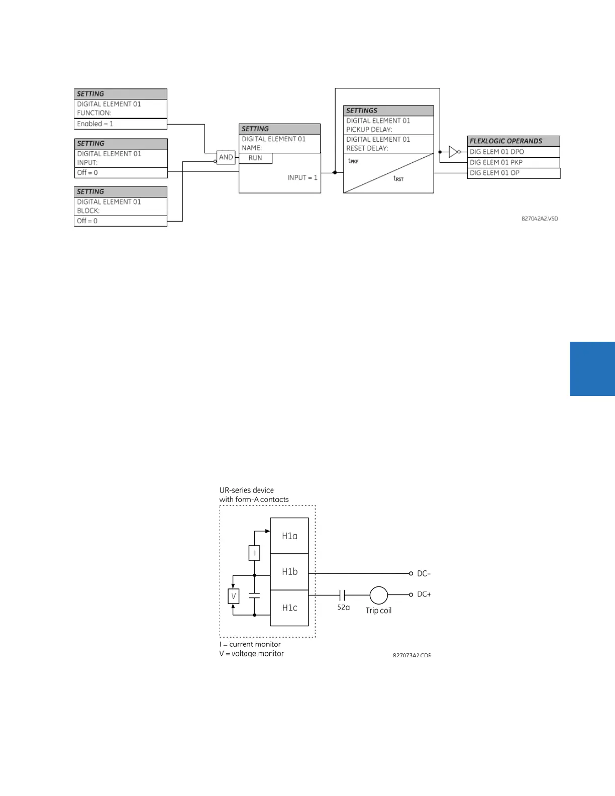
Figure 5-150: Digital element logic
Circuit monitoring applications
Some versions of the digital input modules include an active voltage monitor circuit connected across form-A contacts.
The voltage monitor circuit limits the trickle current through the output circuit (see technical specifications for form-A).
As long as the current through the voltage monitor is above a threshold (see technical specifications for form-A), the Cont
Op 1 VOn FlexLogic operand is set (for contact input 1—corresponding operands exist for each contact output). If the output
circuit has a high resistance or the DC current is interrupted, the trickle current drops below the threshold and the Cont Op 1
VOff FlexLogic operand is set. Consequently, the state of these operands can be used as indicators of the integrity of the
circuits in which form-A contacts are inserted.
Example 1: Breaker trip circuit integrity monitoring
In many applications it is desired to monitor the breaker trip circuit integrity so that problems can be detected before a trip
operation is required. The circuit is considered to be healthy when the voltage monitor connected across the trip output
contact detects a low level of current, well below the operating current of the breaker trip coil. If the circuit presents a high
resistance, the trickle current falls below the monitor threshold, and an alarm is declared.
In most breaker control circuits, the trip coil is connected in series with a breaker auxiliary contact that is open when the
breaker is open (see figure). To prevent unwanted alarms in this situation, the trip circuit monitoring logic must include the
breaker position.
Figure 5-151: Trip circuit example 1