5-318 F35 MULTIPLE FEEDER PROTECTION SYSTEM – INSTRUCTION MANUAL
INPUTS/OUTPUTS CHAPTER 5: SETTINGS
5
DIRECT INPUT 5 DEVICE ID = “2”
DIRECT INPUT 5 BIT NUMBER = “12”
UR IED 2:
DIRECT OUT 12 OPERAND = “Cont Ip 1 On”
The Cont Ip 1 On operand of UR IED 2 is now available in UR IED 1 as
DIRECT INPUT 5 ON.
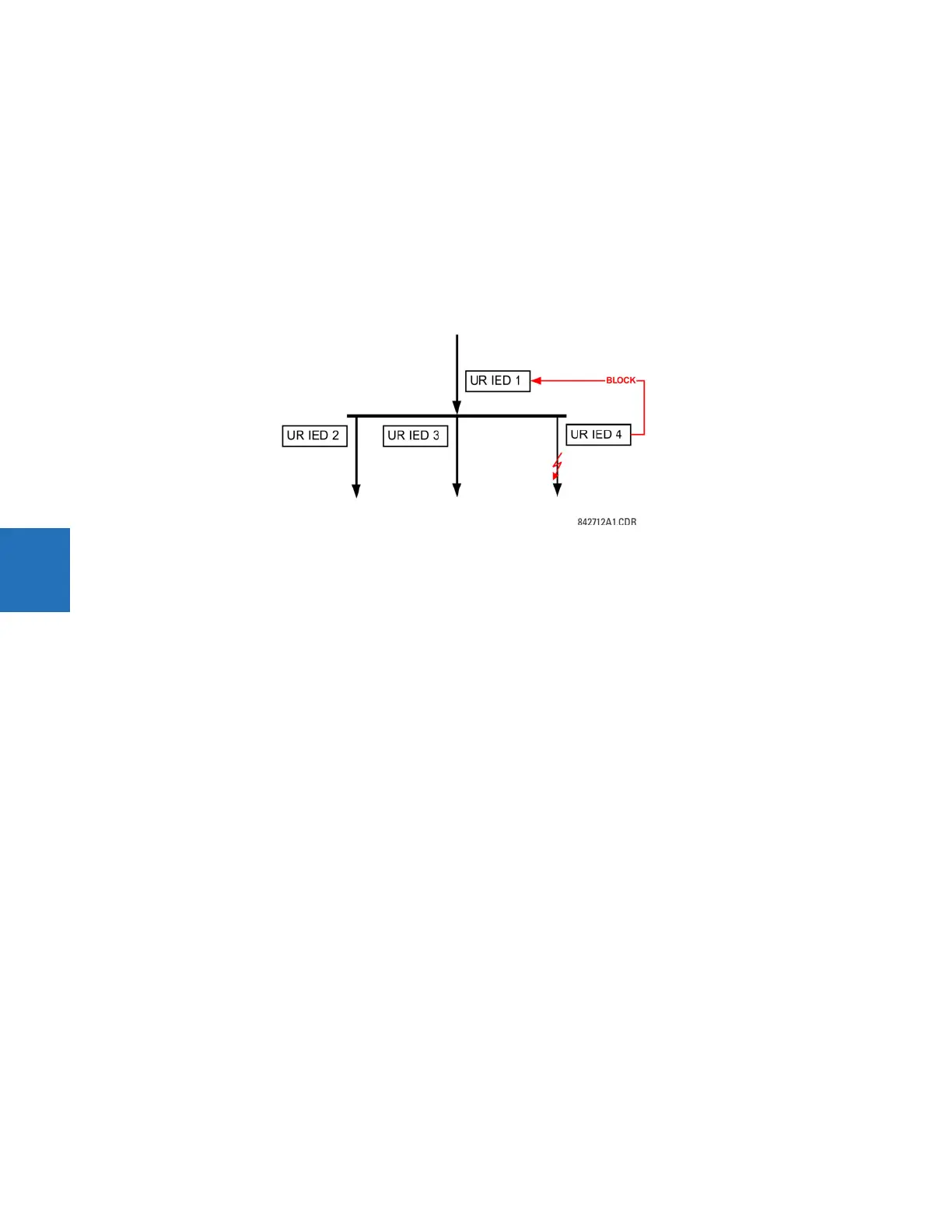
Example 2: Interlocking busbar protection
A simple interlocking busbar protection scheme can be accomplished by sending a blocking signal from downstream
devices, say 2, 3 and 4, to the upstream device that monitors a single incomer of the busbar, as shown in the figure.
Figure 5-178: Sample interlocking busbar protection scheme
Assume that Phase Instantaneous Overcurrent 1 is used by Devices 2, 3, and 4 to block Device 1. If not blocked, Device 1
trips the bus upon detecting a fault and applying a short coordination time delay.
The following settings are applied (assume Bit 3 is used by all 3 devices to send the blocking signal and Direct Inputs 7, 8,
and 9 are used by the receiving device to monitor the three blocking signals).
UR IED 2:
DIRECT OUT 3 OPERAND: "PHASE IOC1 OP"
UR IED 3:
DIRECT OUT 3 OPERAND: "PHASE IOC1 OP"
UR IED 4:
DIRECT OUT 3 OPERAND: "PHASE IOC1 OP"
UR IED 1:
DIRECT INPUT 7 DEVICE ID: "2"
DIRECT INPUT 7 BIT NUMBER: "3"
DIRECT INPUT 7 DEFAULT STATE: select "On" for security, select "Off" for dependability
DIRECT INPUT 8 DEVICE ID: "3"
DIRECT INPUT 8 BIT NUMBER: "3"
DIRECT INPUT 8 DEFAULT STATE: select "On" for security, select "Off" for dependability
DIRECT INPUT 9 DEVICE ID: "4"
DIRECT INPUT 9 BIT NUMBER: "3"
DIRECT INPUT 9 DEFAULT STATE: select "On" for security, select "Off" for dependability
Now the three blocking signals are available in UR IED 1 as
DIRECT INPUT 7 ON, DIRECT INPUT 8 ON, and DIRECT INPUT 9 ON. Upon losing
communications or a device, the scheme is inclined to block (if any default state is set to “On”), or to trip the bus on any
overcurrent condition (all default states set to “Off”).
Example 3: Pilot-aided schemes
Consider a three-terminal line protection application shown in the following figure.