EasyManuals Logo

GE F35 User Manual

GE F35
682 pages
To Next Page IconTo Next Page
To Previous Page IconTo Previous Page
Page #602 background imageLoading...
Page #602 background image
10-20 F35 MULTIPLE FEEDER PROTECTION SYSTEM – INSTRUCTION MANUAL
REPLACE FRONT PANEL CHAPTER 10: MAINTENANCE
10
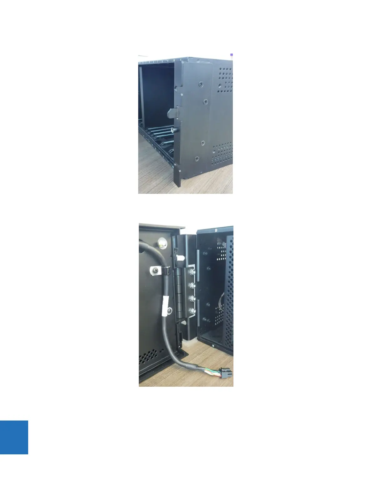
Figure 10-20: Attach mounting bracket to relay on right side
3. Attach the graphical front panel hinge to the left mounting bracket using the nuts provided.
Figure 10-21: Attach to left mounting bracket inside relay
4. Close the front panel without tightening the screw to the mounting bracket.
5. Optionally remove the protective plastic film on the graphical front panel. It is normally peeled off, but also can be left
on.
The graphical front panel has been installed but not connected.

Table of Contents

Questions and Answers:

Question and Answer IconNeed help?

Do you have a question about the GE F35 and is the answer not in the manual?

GE F35 Specifications

General IconGeneral
Frequency50/60 Hz
Device FunctionProtection Relay
Communication ProtocolsDNP3
TypeDigital Protection Relay
Current Rating5 A
Protection FunctionsOvercurrent

Related product manuals