GEK-113000AE F650 Digital Bay Controller 1-11
1 GETTING STARTED 1.2 OVERVIEW
1
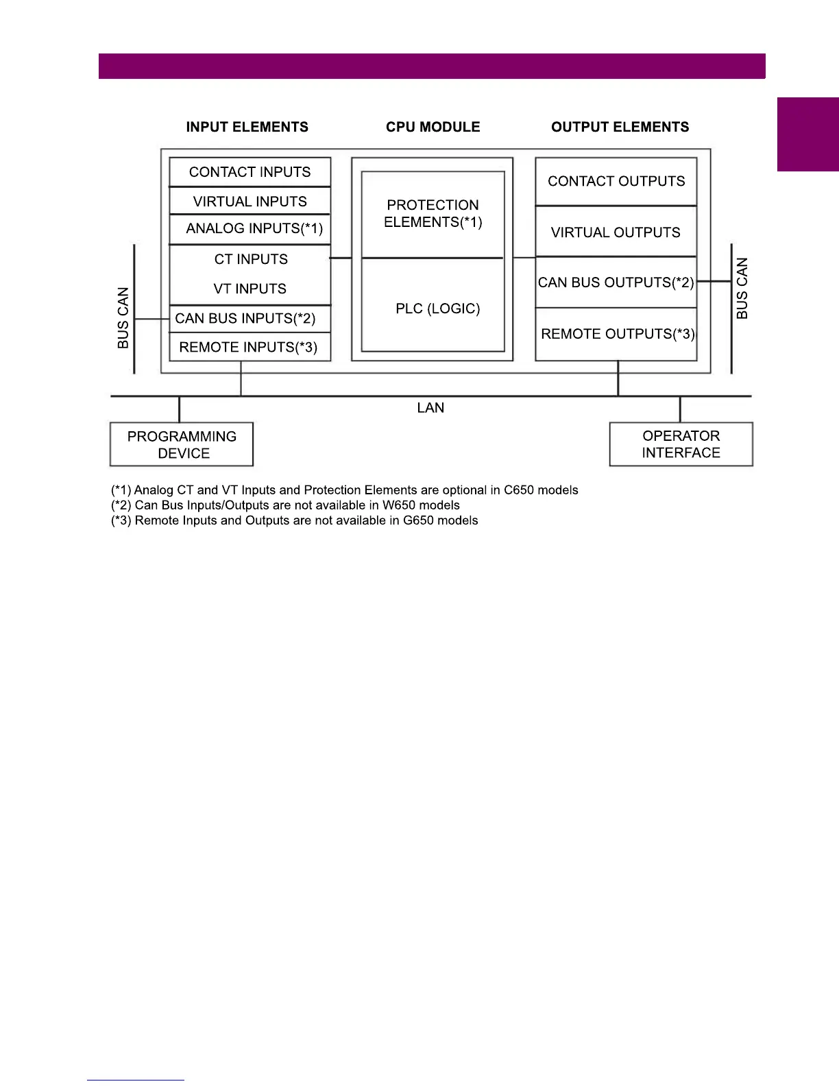
Figure 1–6: 650 CONCEPT BLOCK DIAGRAM
b) F650 SIGNAL TYPE
Contact Inputs/Outputs are digital signals.
CT and VT inputs: are signals coming from the inputs of current and voltage transformers, used for monitoring the power
system signals.
CAN Bus Inputs/Outputs: are signals associated to physical input/output contacts from independent modules connected to
the 650 unit via a CAN Bus.
PLC: Programmable Logic Controller. Control module that enables the unit configuration (assignment of inputs/outputs)
and the implementation of logic circuits.
Protection Elements: Relay protection elements, for example: Overcurrent, overvoltage, etc.
Remote inputs and outputs provide a means of sharing digital point state information between remote devices using IEC
61850 GSSE and GOOSE messages.
Analog Inputs are signals associated with transducers.

 Loading...


