GEK-113000AE F650 Digital Bay Controller 6-9
6 COMMISSIONING 6.8 VERIFICATION OF MEASUREMENT
6
Percent of Load-to-Trip
The relevant actual values displays are shown below:
ACUAL -> METERING -> PRIMARY VALUES -> CURRENT -> % OF LOAD-TO-TRIP
Note Percent of load-to-trip is calculated from the phase with the highest current reading. It is
the ratio of this current to the lowest pickup setting among the phase time and instantaneous overcurrent protection
features. If all of these features are disabled, the
value displayed will be “0”.
- Inject current of various values into Phase A.
- Verify that percent load-to-trip is calculated as the correct
percentage of the most sensitive operational Phase Overcurrent
element and displayed.
- Repeat for phases B and C.
6.8.3 ACTIVE, REACTIVE POWER, AND COSJ METERING
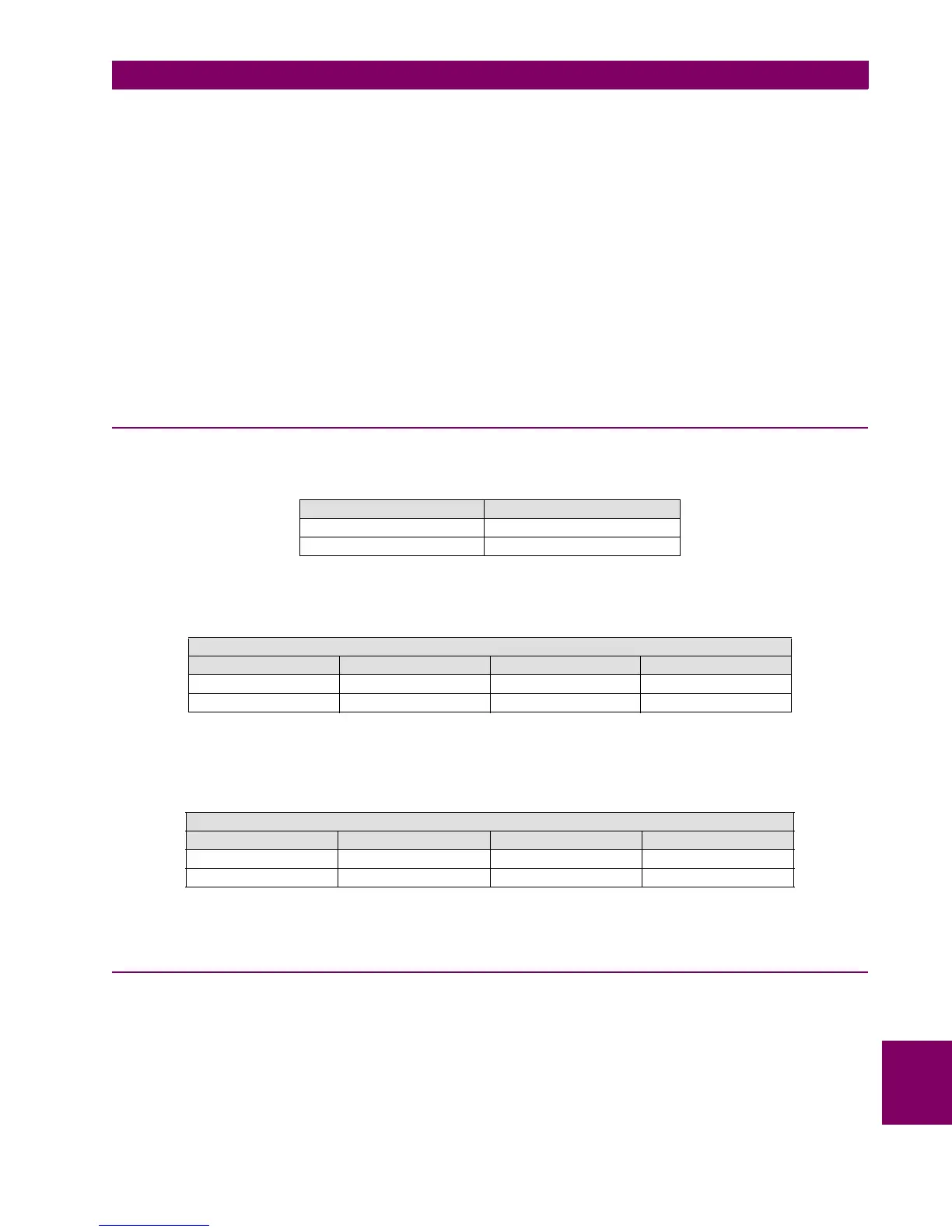
Equations to be applied for powers in a wye connection are as follows:
Apply the following current and voltage values:
With the indicated voltage and current values, verify that the power measure corresponds to expected values indicated in
the following table:
Maximum admissible error is ± 1% of the test value for P and Q, and 0.02 for cosj.
6.8.4 FREQUENCY
Frequency measure on channel VII (terminals A7-A8):
Apply 50 Vac at 50 Hz on channel VII. Maximum admissible error:± 10 mHz.
Apply 50 Vac at 60 Hz on channel VII. Maximum admissible error: ± 12 mHz.
Frequency measure on channel Vx (terminals A11-A12):
POWER PER PHASE THREE-PHASE POWER
P=V*I*Cosϕ P=Pa+Pb+Pc
Q=V*I*Senϕ Q=Qa+Qb+Qc
APPLIED VOLTAGE AND CURRENT VALUES PER PHASE
PHASE A PHASE B PHASE C V-I ANGLES
VI = 50 V, 0º VII = 50 V , 120º VIII = 50V, 240º ϕ=45º
Ia = 10∠45º Ib= 10∠165º Ic = 10∠285º Cosϕ= 0.707
EXPECTED POWER VALUES
PHASE A PHASE B PHASE C THREE-PHASE
Pa = 353.55 MW Pb = 353.55 MW Pc = 353.55 MW P = 1060.66 MW
Qa = 353.55 MVAr Qb = 353.55 MVAr Qc = 353.55 MVAr Q = 1060.66 MVAr