EasyManuals Logo

GE F650 User Guide

GE F650
323 pages
To Next Page IconTo Next Page
To Previous Page IconTo Previous Page
Page #201 background imageLoading...
Page #201 background image
GEK-113000AE F650 Digital Bay Controller 6-19
6 COMMISSIONING 6.13 DIRECTIONAL ELEMENTS (67P, 67N, 67G, 67SG)
6
6.13.4 67SG ELEMENT
Activate only protection elements 50SG and 67SG and set the relay as follows:
Configure one of the outputs to be activated only by unit 50SG.
Apply the following tests:
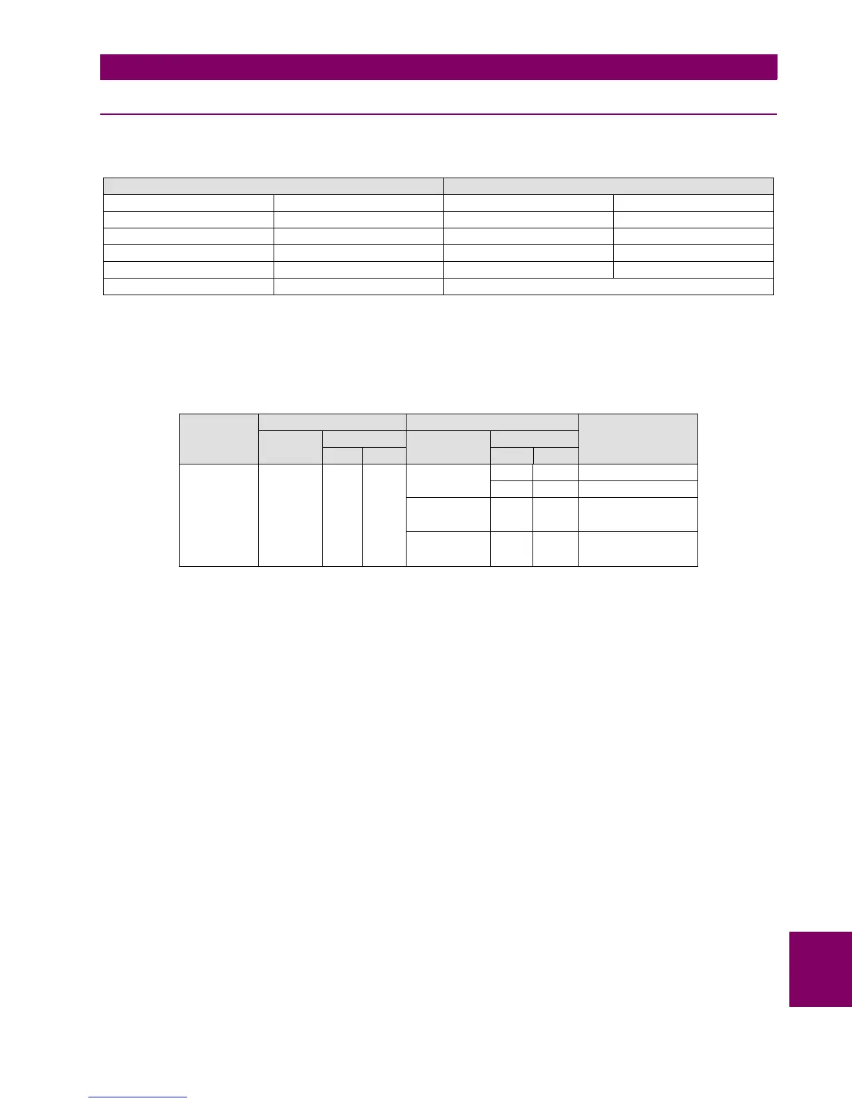
67SG SETTINGS 50SG SETTINGS
Function ENABLED Function ENABLED
MTA -45 Deg Input PHASOR (DFT)
Direction FORWARD Pickup Level 0.50 A
Polarization VO Trip Delay 0.30
Block Logic PERMISSION Reset Delay 0.00
Pol V Threshold 10 V
ELEMENTS PHASE UNDER TEST POLARIZATION PHASE ELEMENT TRIP
CHANNEL MAGNITUDE CHANNEL MAGNITUDE
MOD ARG MOD ARG
50SG/67SG ISG 2 A VI 60 V NO
60 V 180º YES
VII 0 V
VIII 0 V

Table of Contents

Other manuals for GE F650

Questions and Answers:

Question and Answer IconNeed help?

Do you have a question about the GE F650 and is the answer not in the manual?

GE F650 Specifications

General IconGeneral
ModelF650
CategoryController
Frequency50/60 Hz
DisplayLCD
TypeFeeder Protection Relay
ApplicationFeeder Protection and Control
Communication ProtocolsDNP3, Modbus, IEC 61850
Protection FunctionsOvercurrent, Earth Fault
ManufacturerGeneral Electric
Input Voltage24-250 VDC/VAC

Related product manuals