GEK-113000AE F650 Digital Bay Controller 2-33
2 PRODUCT DESCRIPTION 2.5 TECHNICAL SPECIFICATIONS
2
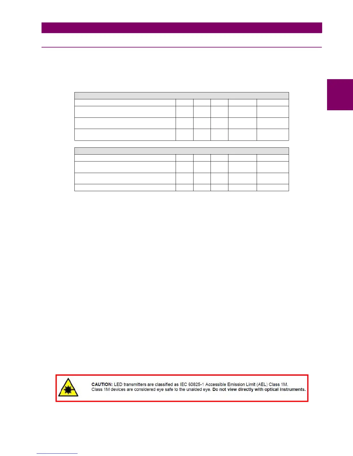
2.5.11 OPTIC FEATURES
Wave length: 1300nm
Connector types: ST package style
Fiber type: multimode 62.5/125 mm or 50/125 mm
Notes:
1. These optical power values are measured with the following conditions:
The Beginning of Live (BOL) to the End of Life (EOL) optical power degradation is typically 1.5 dB per industry
convention for long wavelength LEDs. The actual degradation observed in Agilent’s 1300nm LED products is <1 dB, as
specified in this data sheet.
Over the specified operating voltage and temperature ranges.
With HALT Line State, (12.5 MHz square-wave), input signal.
At the end of one meter of noted optical fiber with cladding modes removed.
The average power value can be converted to a peak power value by adding 3 dB. Higher output optical power
transmitters are available on special request.
2. The transmitter provides compliance with the need for Transmit_Disable commands from the FDDI SMT layer by
providing an Output Optical Power level of <-45 dBm average in response to a logic “0” input. This specification applies
to either 62.5/125 mm or 50/125 mm fiber cables.
3. This specification is intended to indicate the performance of the receiver section of the transceiver when Input Optical
Power signal characteristics are present per the following definitions. The Input Optical Power dynamic range from the
minimum level (with a window time-width) to the maximum level is the range over which the receiver is guaranteed to
provide output data with a Bit Error Ratio (BER) better than or equal to 2.5e-10.
At the Beginning of Life (BOL).
Over the specified operating temperature and voltage ranges.
4. All conditions for Note 3 apply except that the measurement is made at the center of the symbol with no window time-
width.
TRANSMITTER CHARACTERISTICS
Parameter Min. Typ. Max. Unit Reference
Output Optical Power BOL
62.5/125 μm, NA = 0.275 Fiber EOL
-19
-20
-14 dBm avg. Note 1
Output Optical Power BOL
50/125 μm, NA = 0.275 Fiber EOL
-22.5
-23.5
-14 dBm avg. Note 1
Output Optical Power at
Logic “0” State
-45 dBm avg. Note 2
RECEIVER CHARACTERISTICS
Parameter Min. Typ. Max. Unit Reference
Input Optical Power
Minimum at Window Edge
-33.9 -31 dBm avg. Note 3
Input Optical Power
Minimum at Eye Center
-35.2 -31.8 dBm avg. Note 4
Input Optical Power Maximum -14 dBm avg. Note 3

 Loading...


