GEK-113000AE F650 Digital Bay Controller B-1
APPENDIX B B.1 PRP AND HSR ETHERNET PROTOCOLS
B
APPENDIX B REDUNDANCY PROTOCOLSB.1 PRP AND HSR ETHERNET PROTOCOLS
Industrial real-time Ethernets typically demand much higher availability and uninterrupted operation than office Ethernet
solutions can provide. Even a short loss of connectivity can result in loss of functionality, as for example in some
automation, vehicular, power generation, and power distribution systems.
To recover from a network failure, different standard redundancy schemes are applied such as Parallel Redundancy
Protocol (PRP), High-availability Seamless Redundancy (HSR) and others.
The basic concept of both protocols, PRP and HSR, is to send practically identical frames over different paths and discard
one of the copies in reception, at best. If an error occurs or one of the paths is down, the frame travelling through that path
will not reach its destination, but its copy will.
If the node to be attached to a redundant network has not the capability to do it (e.g. has only one p ort), it could be
connected through a Redundancy Box (RedBox). This type of node allows single attached nodes connect transparently to
a redundant network. An example can be seen in Figures 1.
PRP operates on two independent networks. Each frame is replicated on the sending node and transmitted over both
networks. The receiving node processes the frame arriving first and discards the subsequent copy. The PRP layer is
responsible for this replicate/discard function and hides the two networks from the upper layers. This scheme works without
explicit reconfiguration and switchover and therefore does not show a period of unavailability.
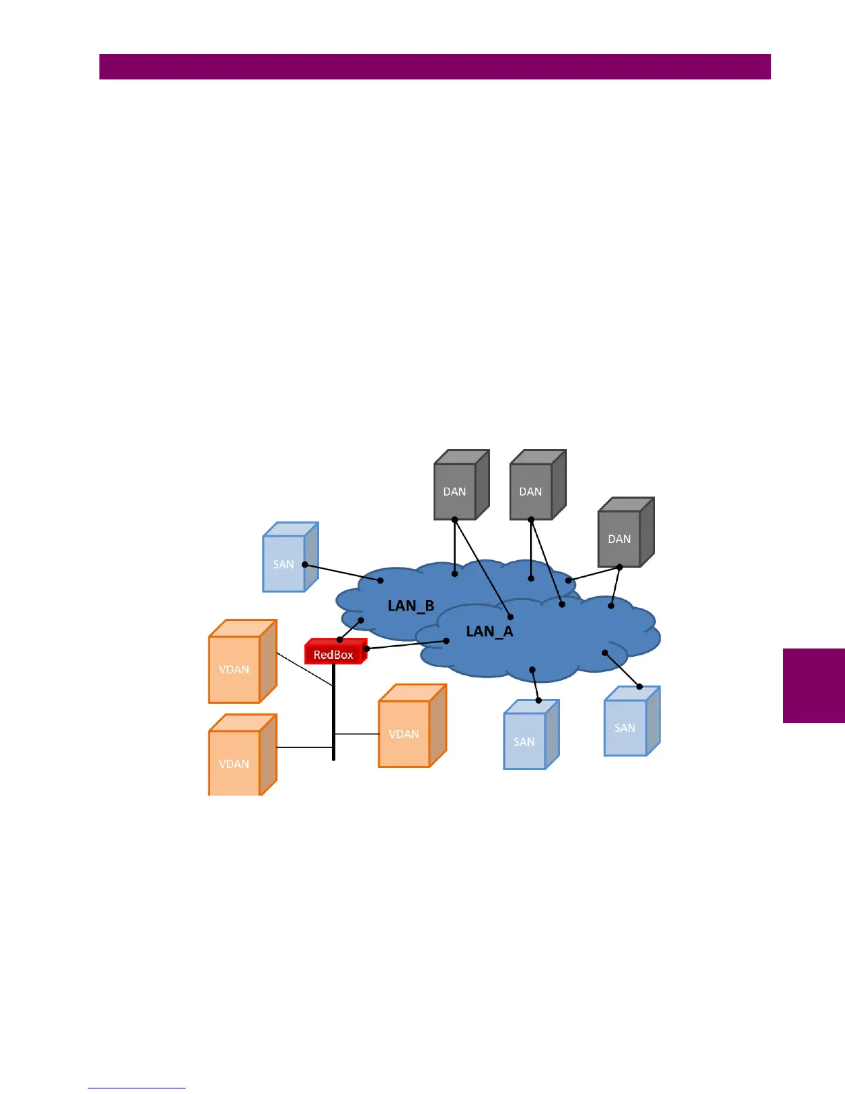
Figure B–1: EXAMPLE OF PRP WITH TWO LANS (LAN A AND LAN B)
The two LANs, named LAN_A and LAN_B, are identical in protocol at the MAC level, but they can differ in performance and
topology. Transmission delays can also be different. The LANs have no direct connection among them and they are
assumed to be fail independent.
In some applications, only availability-critical nodes need a double attachment, while others do not. In order to meet the
specific requirements, PRP defines different kinds of end nodes.
• The Dual Attached Node (DAN) is connected to both LANs.
• Uncritical nodes can be attached to only one LAN and are therefore called Single Attached Nodes (SAN). SANs that
need to communicate with each other are on the same LAN.

 Loading...


