GEK-106310AE F650 Digital Bay Controller 3-9
3 HUMAN INTERFACES. SETTINGS & ACTUAL VALUES 3.1 ENERVISTA 650 SETUP SOFTWARE INTERFACE
3
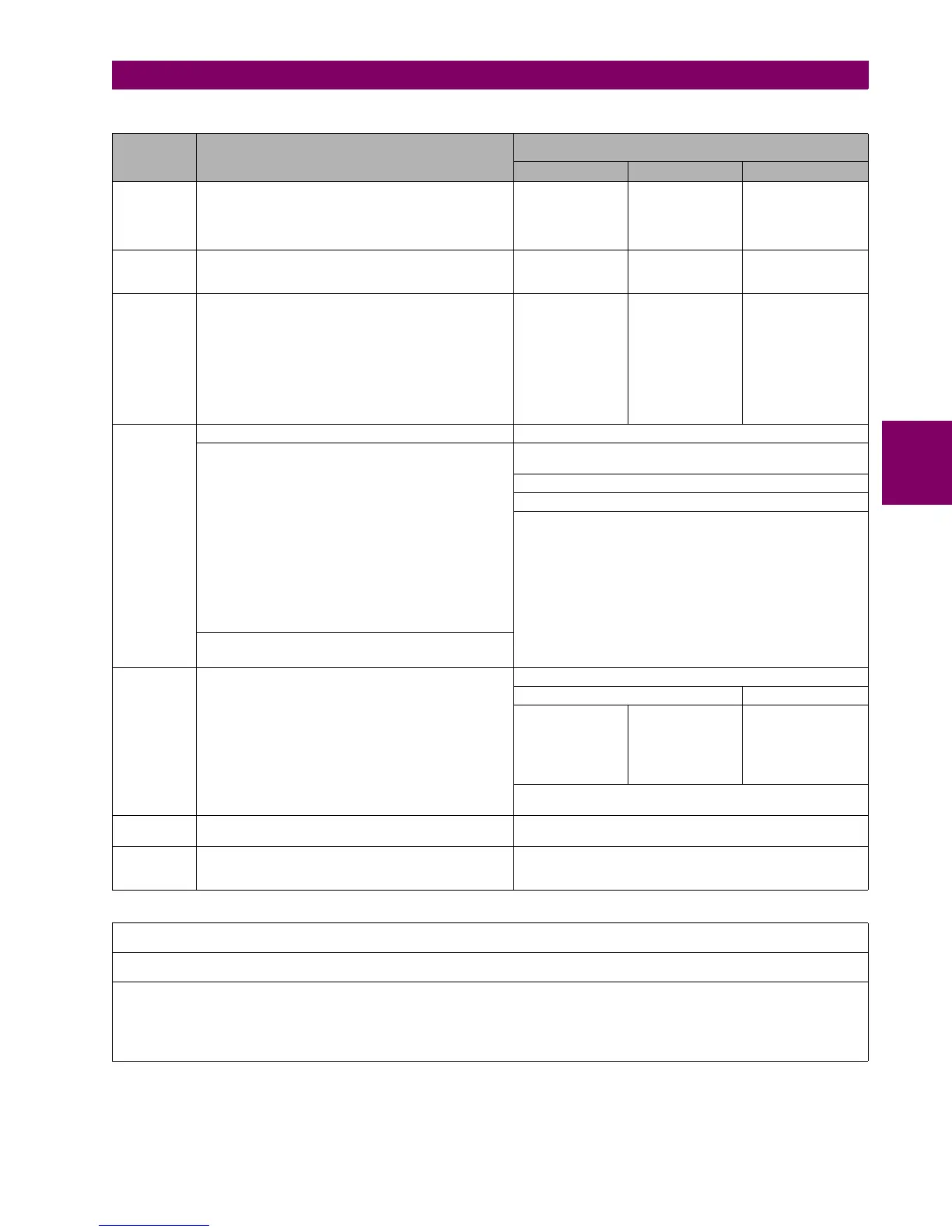
Table 3.2: TYPES OF FILES GENERATED BY ENERVISTA 650 SETUP SOFTWARE OPERATION MODE ON-LINE
SETTINGS & CONFIGURATION FILE *.650
LOGIC CONFIGURATION FILES (*.PEP, *.AUT, *.LIB)
*.PEP *.AUT *.LIB
Description Settings and Configuration Section
Header for Logic
project
Graphical edition
container. Logic
equations (Virtual
Outputs) in FDB
format.
User programmable
logic objects
Created by EnerVista 650 Setup
Logic configuration
graphic editor (PLC
Editor)
Logic configuration
graphic editor (PLC
Editor)
Logic configuration
graphic editor (PLC
Editor)
Contents
Relay configuration file containing all elements, settings,
input/output and LEDs configuration, graphic display
configuration, etc.
Equations corresponding to the logic created and
compiled in the PLC Editor
PLC project file
containing the
necessary
information relative
to the relay model,
logic libraries
included in the
project (*.lib),
graphic file name
(*.aut), etc.
PLC Project file
containing all the
drawings used by
the logic, required
by 650 relay based
on IEC 61131-3
standard.
Functional block
diagram (FDB).
Library file to be
included as an object
in a PLC project.
Logic packages that
can be stored into
libraries and be
distributed in different
PLC projects.
How to
transfer to
relay
Connect with the relay ("Communications>Computer") Connect with the relay ("Communications>Computer")
Send settings and configuration from file
Launch 650 Logic equations editor ("Setpoint>Logic
Configuration")
Open the created PLC project ("File>Open Project")
Compile the project ("Run>Compile")
Now the logic (virtual outputs) can be sent directly to relay
("Run>Send Equations to Relay"). Texts of virtual outputs are
not stored in the relay, only in the logic configuration files to be
edited.
Modify settings and configuration directly in the relay:
How to save
EnerVista 650 Setup:
"File>Get info from relay". User definable texts
retrieved are operations, events, and LEDs.
PLC Editor:
"File>Save Project" "File>Save Library"
The relay will not
provide this
information unless
the *.pep file is
stored in the relay
The relay will not
provide this
information unless
the *.pep file is
stored in the relay.
The relay will not
provide this
information unless
the *.pep file is stored
in the relay.
To store the logic configuration files in the relay use the
"Communication>Upload info files to relay" option
How to store
in the relay
"Communication>Upload info files to relay" through
Ethernet
"Communication>Upload info files to relay" through
Ethernet
How to
retrieve from
the relay
"Communication/Download info files from relay"
through Ethernet
"Communication/Download info files from relay" through
Ethernet
REMINDER:
Logic programming support files (*.pep, *.aut, *.lib) CANNOT be retrieved directly from the relay.
It is necessary
* Either to have stored these files in the PC
* Or to have uploaded previously the files into the relay ("Communication>Upload info files to relay")
 Loading...


