22
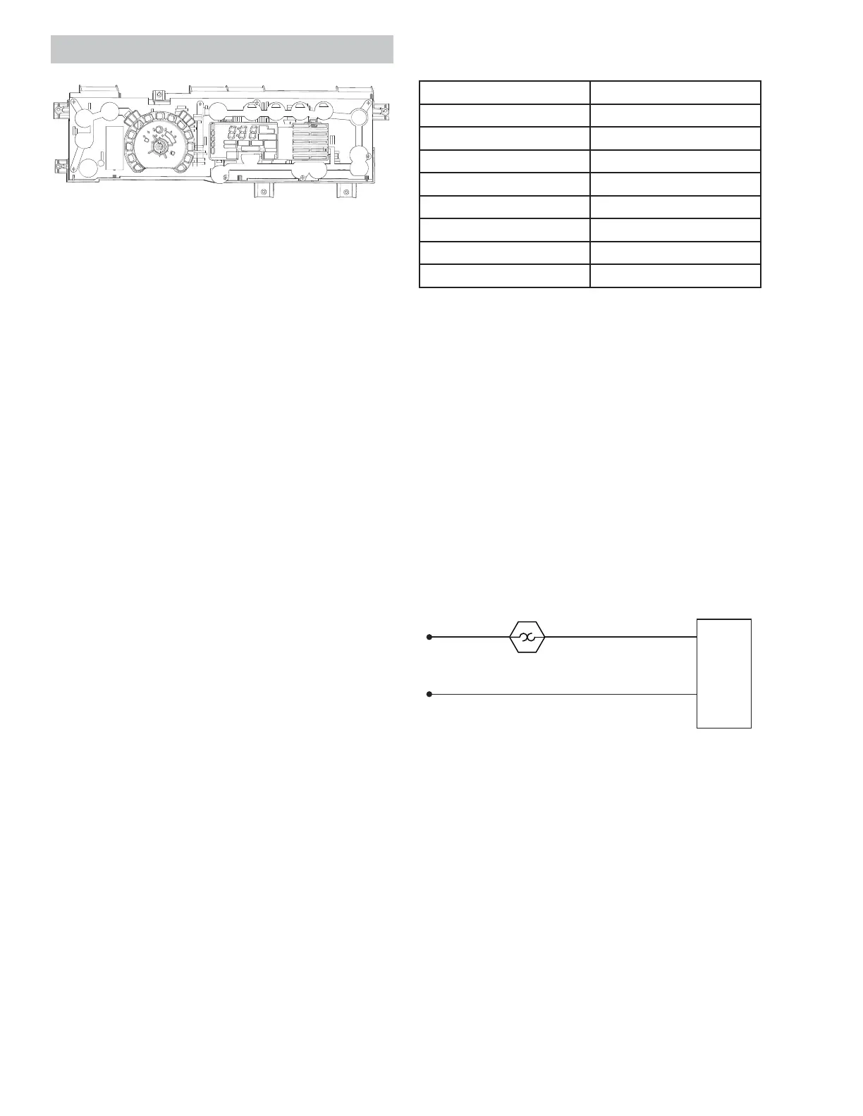
Main Control Board
Operating Voltage: 120 VAC
Th e m a in co nt r ol b oa r d i s t w o el ect r o ni c b oa rd s
connected together by a wire spline and mounted in
a plastic housing. The front board is the User Inter-
face (UI) board and the rear board is the Machine
Co nt r o l b o a r d.
When the main control board is replaced, the new
board MUST be programmed with a model ID code.
Th e m od el ID co nsi st s o f t h e "User In t er f a ce Mo de
Ty p e " a n d t h e " Hea t e r Ty p e" .
Th e User In t er f a ce Mo de Typ e i s a nu m ber c ur r en t l y
between 0 and 3. The Heater Type will be either an
"E" for electric or a "g" for gas. Follow the instruc-
tions below to program the board.
When the main control board has been replaced, it
may sometimes power up with all of the LED's blink-
ing. If this is the case, follow only steps 5 through
10 below. Otherwise, follow all of the steps from the
beginning.
Main Control Board Model ID Programming
1. Begin with the dryer in Idle Mode (all LED's on
GLVSOD\RȺ
2. Press the following key sequence to enter Ser-
vice Mode: My Cycle --> Delay Dry --> My Cycle
--> Delay Dry.
NOTE: Th e seq uen ce m u st b e d on e i n or d er. If
there are any other button presses or buttons
are pressed out of order, the sequence must be
started from the beginning.
3. Upon entering Service Mode, the control will be
in t1.
4. Press the St a r t / Pa u s e button when "t1" is dis-
played.
5. Simultaneously press and hold both the Temp &
Level buttons for three seconds to prepare the
control for selecting the model.
6. Press the Level button to increase or press
the Tem p button to decrease the Model Code
number selection until the correct number is
displayed, per the table on the right.
User Interface Mode Type Table
(See par t in st r uct i o n s if mo d el is not li st ed i n t ab l e.)
GFMR2 95EF/ GF 0
GFDS26 0EF/ GF 1
GFDS26 5EF/ GF 1
GFDR270 EH/ GH 1
GFDR275 EH/ GH 1
GHDS360 EF/ GF 2
GHDS365 EF/ GF 2
GFDR480 EF/ GF 3
GFDR485 EF/ GF 3
7. Press the St a r t / Pa u s e button to temporarily
save the UI Model Code.
8. Next , the Heater Type selection is displayed as
"g" or Gas or "E" for Electric. Press the Temp or
Level t o alternat e t he 7-segment display be-
tween the two Heater Type selections.
9. Press and hold the Start/Pause button for three
seconds to set the Heater Type. The board will
then return to an idle state and will exit Service
Mode. It could take up to 10 seconds for the
dryer to respond after exiting Service Mode.
10. The dryer is now ready for use.
Main Cont rol Board St rip Circuit
Main Cont rol Board Removal
1. Disconnect power from the unit .
2. Remove the control panel.
3. Disconnect the main control board wire har-
nesses.
4. Remove the six 5/16 in. hex main control board
screws and lift the board out .
Main
Co n t r o l
Board
J1-1
J1-2
Black
N
L1
High Limit
Th er m ost a t
White
Black/ Yellow
See M a i n Co n t r o l Bo a r d L o c a t i o n o n p a g e 16 .
See Co n t r o l Pa n e l Rem o v a l o n p a g e 2 0 .