33
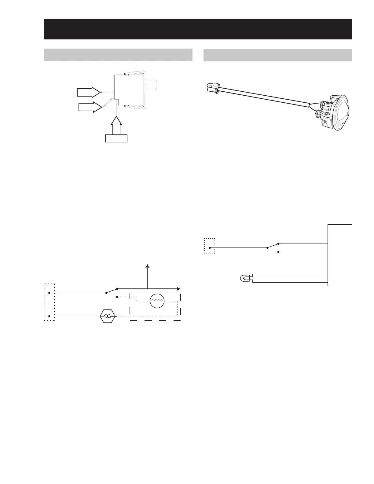
Door Swit ch
N.C.
Oper at i ng Volt age: 120 VAC
SPDT Sw i t c h
Door Closed: Com is connected t o N.O.
Door Open: Com is connected t o N.C.
MCB J1 pin 3 reads the door swit ch posit ion. When
the door is closed, neutral is present at pin 3, when
the door is open neutral is not present at pin 3.
Door Switch Strip Circuit
N
L1
To B e l t Sw i t c h
and Steam Valve
High Limit
Th er m ost a t
Door Sw itch
Drum Lamp
To M CB J1 - 3
(Do or Sen se)
Te r m i n a l
Block
On Some Mod els
Door Swit ch Removal
1. Disconnect power from the unit .
2. Remove the control panel.
3. Remove the front panel.
4. Disconnect the door switch wires and remove
the switch.
LED Dr um Lamp
Operating Voltage: ~ 3 VDC
Resistance: N/ A
LED drum lamps are not present on all mod-
els, some models have an incandescent lamp.
LED Drum Lamp Strip Circuit
N
Door Swit ch
Te r m i n a l
Block
White
Or ang e/ Whit e
MCB
J1-3
J9-1
J9-2
Black
Re d
+DC
GND
LED Drum Lamp Removal
1. Disconnect power from the unit .
2. Remove the control panel.
3. Remove the front panel.
4. Remove the front con-
trol assembly bracket assembly.
5. Squeeze the LED lamp mounting clips and pull
the LED lamp out through the inside of the drum.
Drum and Drive Components
Com
N.O.
See D o o r Sw i t c h Lo c a t i o n o n p a g e 16 .
See Co n t r o l Pa n e l Rem o v a l o n p a g e 2 0 .
See Fr o n t Pa n e l Re m o v a l o n p a g e 2 4 .
See D r u m La m p Lo c a t i o n o n p a g e 17 .
See Incandescent Drum Lamp Section on page 34.
See Co n t r o l Pa n e l Rem o v a l o n p a g e 2 0 .
See Fr o n t Pa n e l Re m o v a l o n p a g e 2 4 .
See Fr o n t Co n t r o l As s em b l y Br a c k et Rem o v a l
on page 25.