25
4. Remove the control panel.
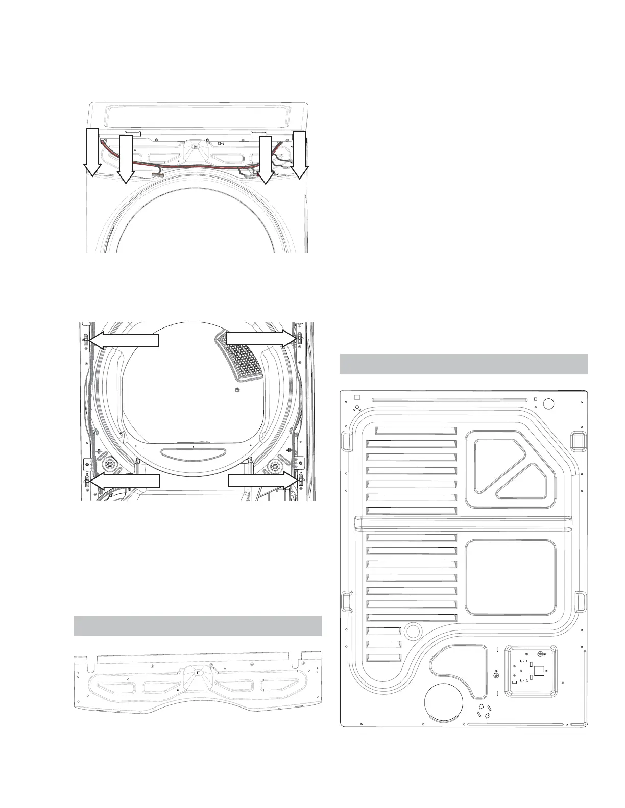
5. Remove the four 1/4 in. hex head screws located
at the top of the front panel.
1/4" hex
1/4" hex
1/4" hex
1/4" hex
6. *UDVS ERWK VLGHV RI WKH IURQW SDQHO DQG ¿UPO\
pull up to disengage the front panel from the side
panel pin supports.
7. Remove the wires from the door switch.
8. If replacing the front panel, transfer the two hinge
VWLȺHQHUVDQGOLJKWVZLWFKWRWKHQHZIURQWSDQHO
NOTE: When reinst alling the front panel, ensure t hat
the door switch wires have been reconnected.
Fr on t Con t r ol Assem bl y Br a cket
Th e f r o nt co nt r ol a ssem b ly br a cket i s u sed t o a t t a ch
the front panel, top panel and control panel and sup-
ports the wire harness.
Fr on t Con t r ol Assemb l y Br acket Rem o v al
1. Disconnect power from the unit .
2. Remove the control panel.
3. Disconnect the main control board wiring.
4. Remove the top panel.
5. Remove the front panel.
6. Remove the two 1/4 in. screws on each side
of the panel. NOTE: The 5/ 16 in. screws do not
have to be removed.
7. If replacing the front control bracket , remove
the ground screw and unfasten the harness wire
ties.
NOTE: When reinstalling t he front cont rol assembly
bracket , make sure the tub light harness is routed
behind the front control assembly bracket.
Re a r Pa n e l
See Co n t r o l Pa n e l Rem o v a l o n p a g e 2 0 .
Pin Support
Pin Support
Pin Support
Pin Support
See Fr o n t Co n t r o l As s em b l y Br a c k et Lo c a t i o n o n
page 17
See Co n t r o l Pa n e l Rem o v a l o n p a g e 2 0 .
See To p Pa n el Rem o v a l o n p a g e 24 .
See Fr o n t Pa n e l Re m o v a l o n p a g e 2 4 .