23
RJ4 5 Bo a r d
RJ45 Bo a r d St r i p Ci r c u i t
RJ 4 5
Board
J4-5
J4-6
J4-7
Main
Co n t r o l
Board
J203-1
J203-2
J203-3
Navy
Ye l l o w
Or ang e
+12 VDC
COMM
DC GND
+12 VDC
COMM
DC GND
RJ45 Board Removal
1. Disconnect power from unit .
2. Remove the control panel.
3. Remove the top panel.
4. Disconnect RJ45 board wire harness.
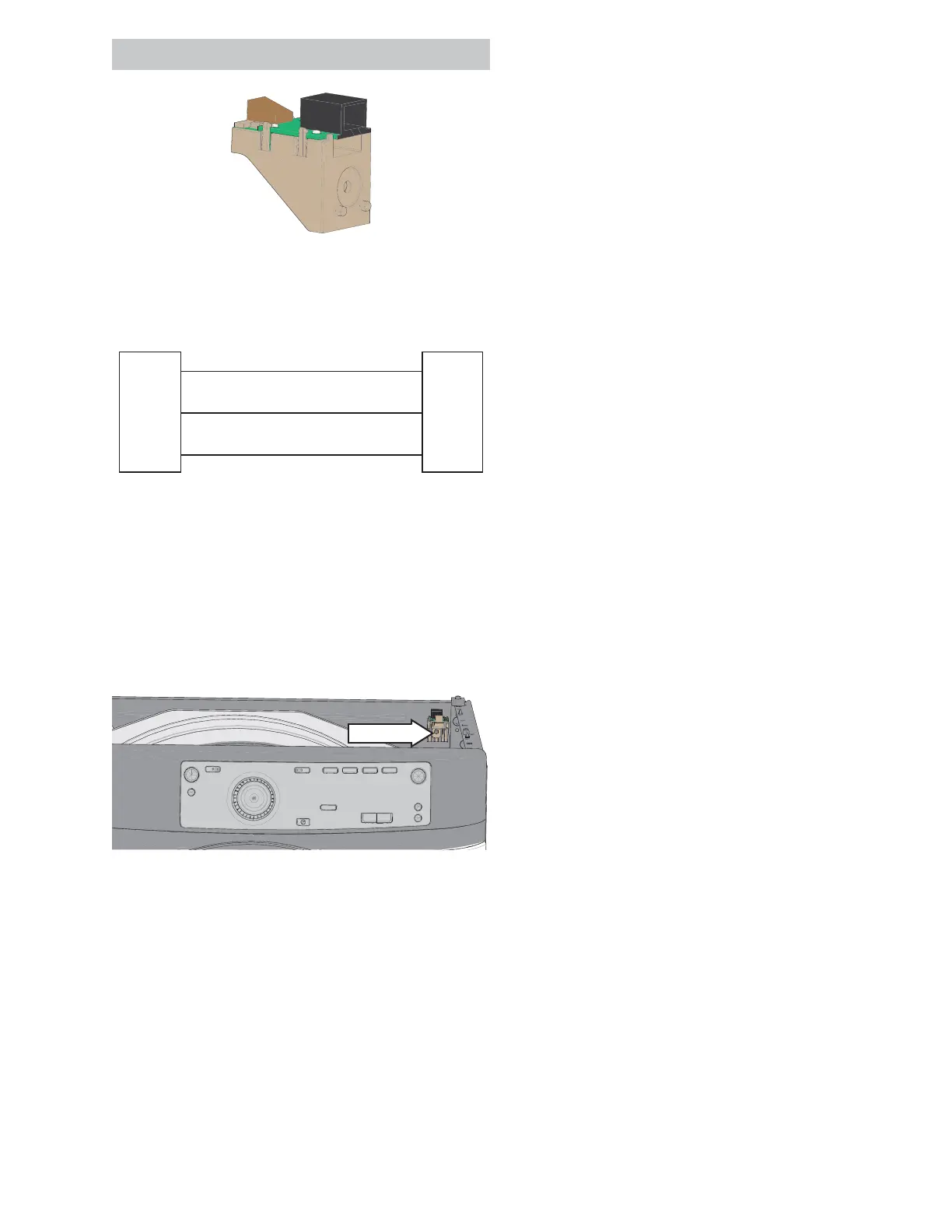
5. Remove the 1/4 in. hex RJ45 board mounting
screw.
1/4" hex
See Co n t r o l Pa n e l Rem o v a l o n p a g e 2 0 .
See To p Pa n el Rem o v a l o n p a g e 24 .