36
11. Remove the steam nozzle.
12. Remove the four 1/4 in. hex screws that hold the
rear drum support to the side panels.
13. Lift the front drum support out of the key holes.
Drum Roller
Th e d r yer u ses f o ur r o ll er s t o sup p or t t h e d r um . The
rollers can be replaced by removing the triangular
FODPSDQGSXOOLQJUROOHUVRȺ
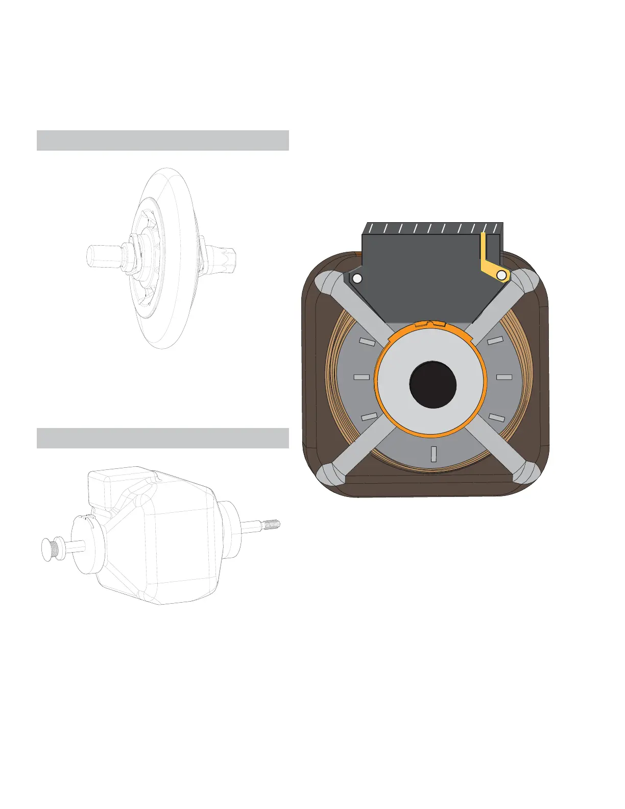
Mot or
7KHPRWRULVORFDWHGRQWKHGU\HUÀRRURQWKHOHIW
side.
Oper at i ng Volt age: 120 VAC Reversible
Horsepower: 1/ 3
R,P.M.: 1725
Main Winding Resistanceű
St a r t W i n d i n g Re s i s t a n c e ű
Th e m ot o r i s u sed t o dr i ve t h e d r u m an d bl ow er
wheel. Motor reversal is accomplished by the drum
reversing relay located on the main control board.
Th e r el ay sw a ps t h e l o ca t i on of l in e a nd n eu t r a l.
Th e m ot o r h as t w o cen t r i f u ga l sw i t c hes t h a t a re l a-
beled A and B on the schematic. Switch A controls L2
to the heater, and switch B connects L1 to either the
start winding when the motor is not running or t o the
main control board when the motor is running.
Mot or Connect or
2 6 8 4 3 9 7 5 1
GND
Pi n 1: Cent rifugal Swit ch A input
Pi n 2: Cent rifugal Swit ch A output
Pi n 3: Cent rifugal Swit ch B N.C.
Pi n 4: Main winding neutral
Pi n 5: Main winding L1
Pi n 6: Cent rifugal Swit ch B N.O.
Pi n 7: St art Winding (Aux 2)
Pi n 8: St art winding (Aux 1)
Pi n 9: Motor TCO out put
Mot or Removal
1. Disconnect power from the unit .
2. Remove the control panel.
3. Remove the front panel.
4. Remove the trap duct .
See Re a r D u c t Rem o v a l o n p a g e 3 9 .
See N o zzl e H o l d e r Rem o v a l o n p a g e 4 9 .
See M o t o r Lo c a t i o n o n p a g e 19 .
See M o t o r D i r e c t i o n 1 H i g h l i g h t o n p a g e 5 1.
See M o t o r D i r e c t i o n 2 Hi g h l i g h t o n p a g e 5 2.
See Co n t r o l Pa n e l Rem o v a l o n p a g e 2 0 .
See Fr o n t Pa n e l Re m o v a l o n p a g e 2 4 .