CHAPTER 5: SETTINGS SYSTEM SETUP
M60 MOTOR PROTECTION SYSTEM – INSTRUCTION MANUAL 5-145
5
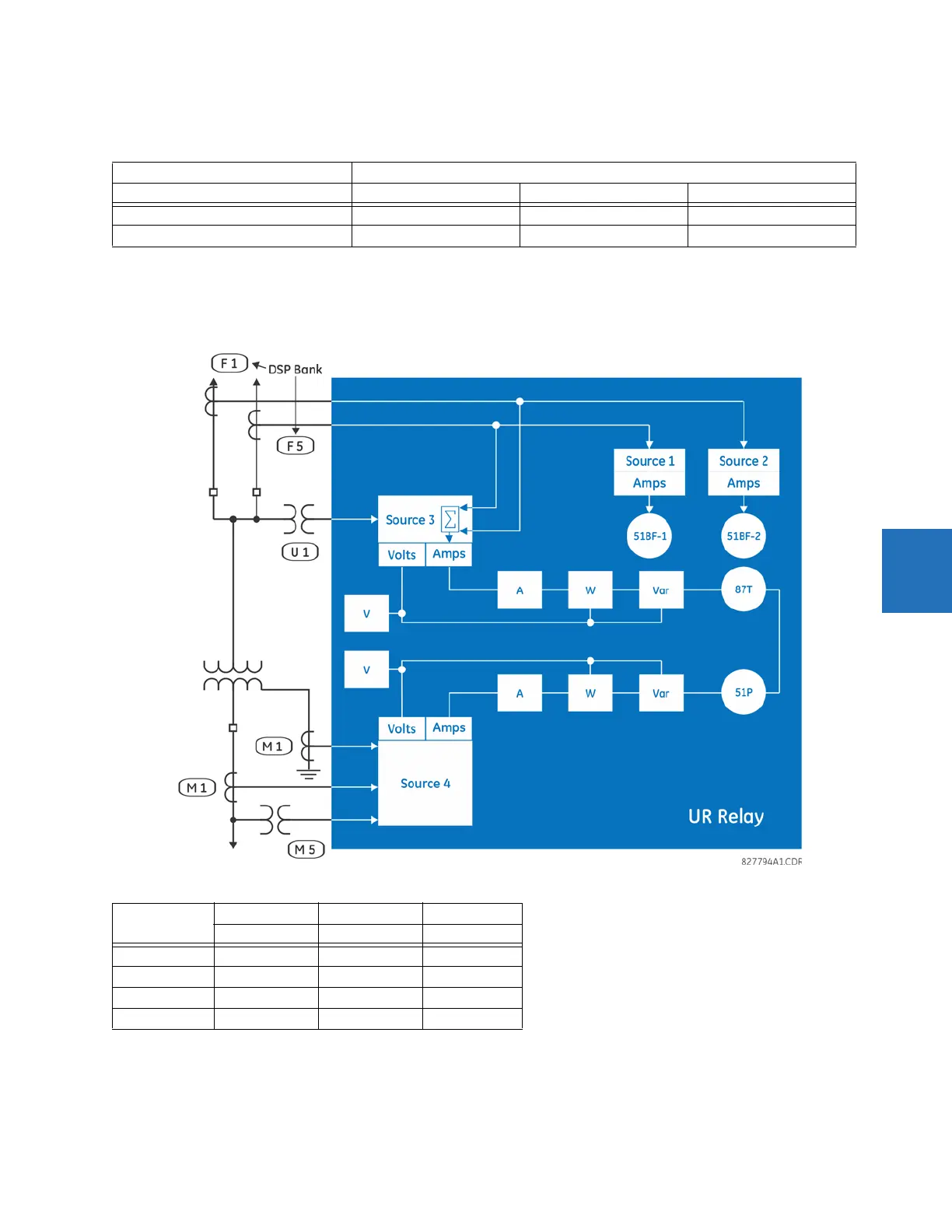
5.5.3.4 Example for use of sources
An example of the use of sources is shown in the following figure. A relay can have the following hardware configuration:
This configuration can be used on a two-winding transformer, with one winding connected into a breaker-and-a-half
system. The following figure shows the arrangement of sources used to provide the functions required in this application,
and the CT/VT inputs that are used to provide the data.
Figure 5-67: Example of use of sources
Increasing slot position letter -->
UR CT/VT module 1 CT/VT module 2 CT/VT module 3
B30, B90, C70, F35, N60, T35 8 CTs 4 CTs, 4 VTs 4 CTs, 4 VTs
C60, D60, G30, G60, L30, L90, M60, T60 CTs VTs not applicable
Y LV D HV AUX
SRC 1 SRC 2 SRC 3
Phase CT M1 F1+F5 None
Ground CT M1 None None
Phase VT M5 None None
Aux VT None None U1