CHAPTER 5: SETTINGS FLEXLOGIC
M60 MOTOR PROTECTION SYSTEM – INSTRUCTION MANUAL 5-189
5
FLEXELEMENT 1 HYSTERESIS — This setting defines the pickup–dropout relation of the element by specifying the width of the
hysteresis loop as a percentage of the pickup value as shown in the FlexElement Direction, Pickup, and Hysteresis diagram.
FLEXELEMENT 1 dt UNIT — Specifies the time unit for the setting FLEXELEMENT 1 dt. This setting is applicable only if
FLEXELEMENT 1 COMP MODE is set to “Delta.”
FLEXELEMENT 1 dt — Specifies duration of the time interval for the rate of change mode of operation. This setting is
applicable only if
FLEXELEMENT 1 COMP MODE is set to “Delta.”
FLEXELEMENT 1 PKP DELAY — Specifies the pickup delay of the element.
FLEXELEMENT 1 RST DELAY — Specifies the reset delay of the element.
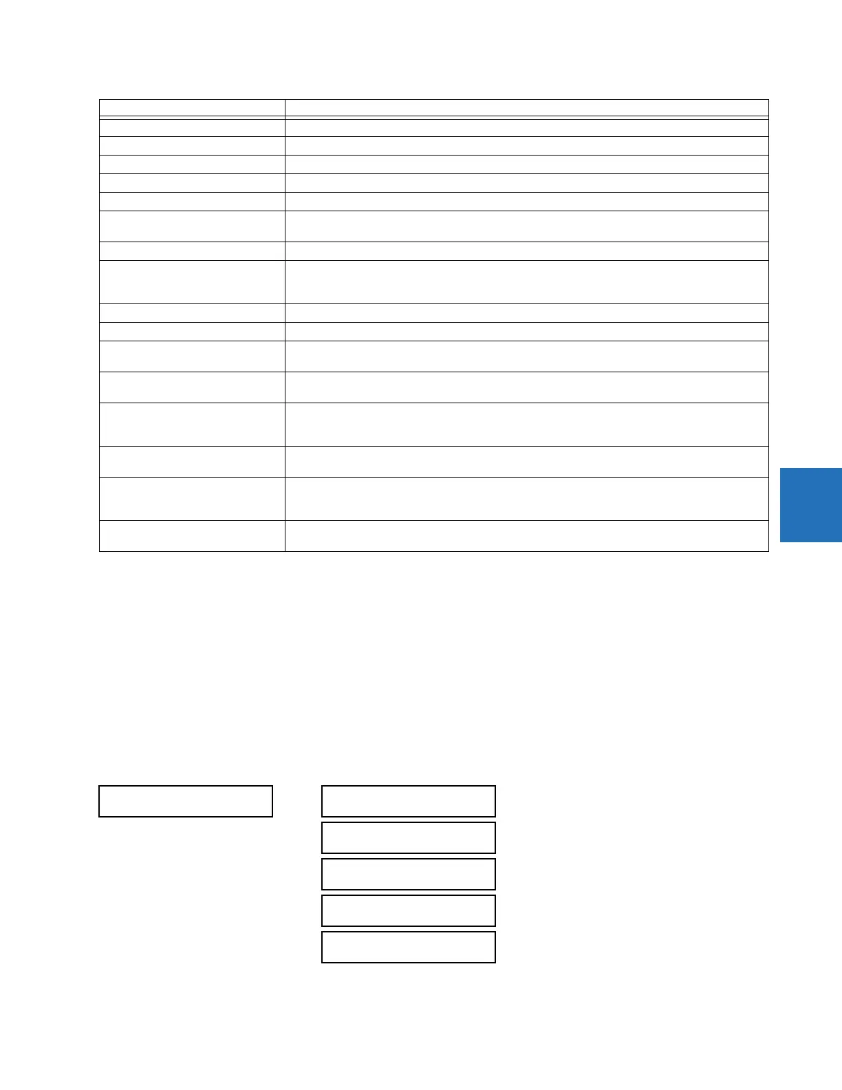
5.6.8 Non-volatile latches
SETTINGS FLEXLOGIC NON-VOLATILE LATCHES LATCH 1(16)
DELTA TIME BASE = 1 µs
FREQUENCY f
BASE
= 1 Hz
PHASE ANGLE ϕ
BASE
= 360 degrees (see the UR angle referencing convention)
POWER FACTOR PF
BASE
= 1.00
RTDs BASE = 100°C
SENSITIVE DIR POWER
(Sns Dir Power)
P
BAS
E
= maximum value of 3 × V
BASE
× I
BASE
for the +IN and –IN inputs of the sources configured
for the sensitive power directional element(s).
SOURCE CURRENT I
BASE
= maximum nominal primary RMS value of the +IN and –IN inputs
SOURCE ENERGY
(Positive and Negative Watthours,
Positive and Negative Varhours)
E
BAS
E
= 10000 MWh or MVAh, respectively
SOURCE POWER P
BASE
= maximum value of V
BASE
× I
BASE
for the +IN and –IN inputs
SOURCE VOLTAGE V
BASE
= maximum nominal primary RMS value of the +IN and –IN inputs
STATOR DIFFERENTIAL CURRENT
(Stator Diff Iar, Ibr, and Icr)
I
BASE
= maximum primary RMS value of the +IN and –IN inputs
(CT primary for source currents, and bus reference primary current for bus differential currents)
STATOR RESTRAINING CURRENT
(Stator Diff Iad, Ibd, and Icd)
I
BASE
= maximum primary RMS value of the +IN and –IN inputs
(CT primary for source currents, and bus reference primary current for bus differential currents)
THERMAL MODEL
(Model Capacity Used)
(Model Motor Unbalance)
BASE =100%
THERMAL MODEL
(Model Lockout Time)
BASE = 10 minutes
THERMAL MODEL
(Thermal Model Load)
(Biased Motor Load)
BASE = 1.00 pu of FLA
THERMAL MODEL
(Trip Time on Overload)
BASE = 10 seconds
LATCH 1
LATCH 1
FUNCTION: Disabled
Range: Disabled, Enabled
LATCH 1 ID:
NV Latch 1
Range: up to 20 alphanumeric characters
LATCH 1 TYPE:
Reset Dominant
Range: Reset Dominant, Set Dominant
LATCH 1 SET:
Off
Range: FlexLogic operand
LATCH 1 RESET:
Off
Range: FlexLogic operand
Unit Description