5-334 M60 MOTOR PROTECTION SYSTEM – INSTRUCTION MANUAL
TRANSDUCER INPUTS/OUTPUTS CHAPTER 5: SETTINGS
5
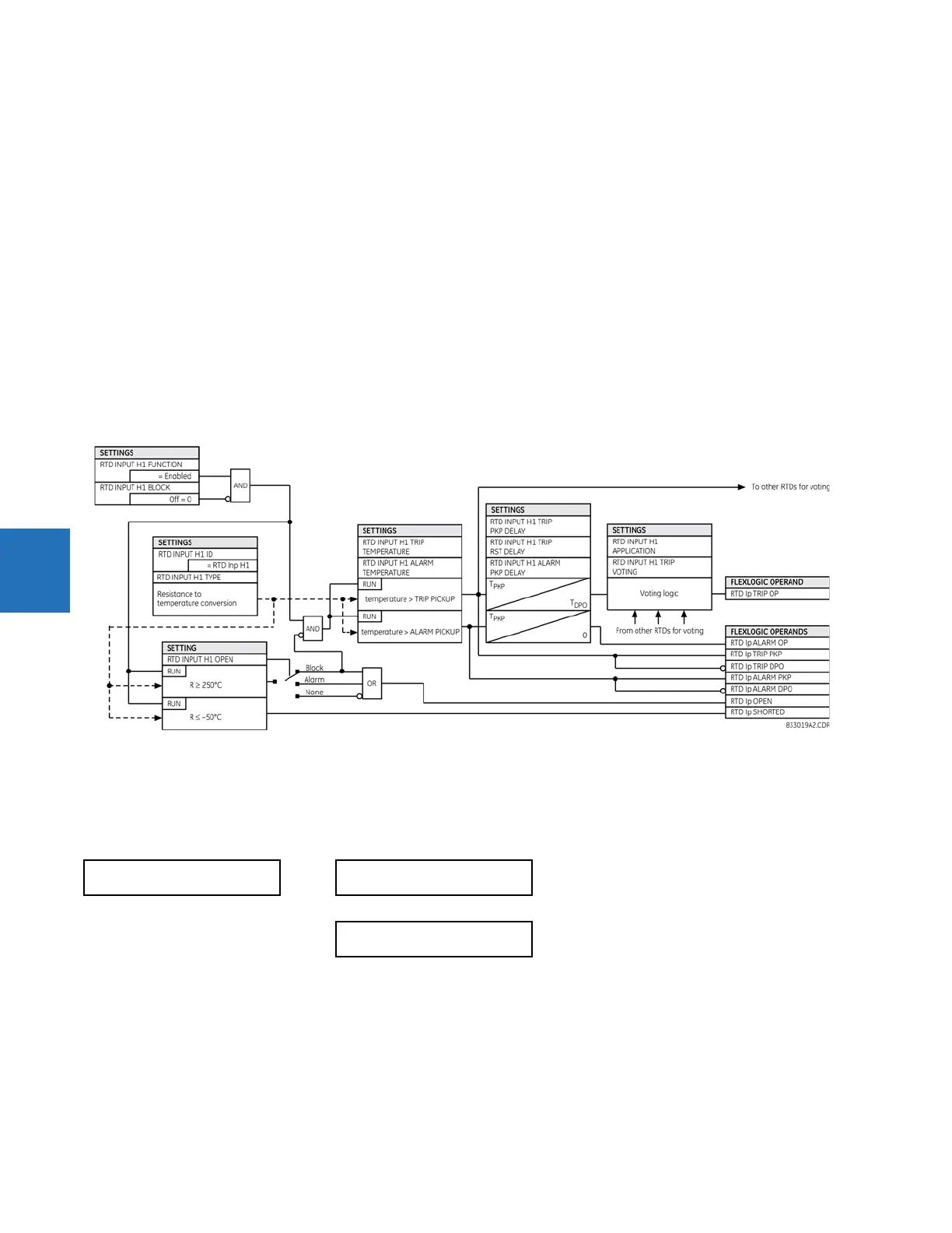
RTD INPUT H1 TRIP VOTING — Allows securing trip signal by voting with other RTDs. A value of “None” indicates that element
operates individually and no voting takes place.
A value of “Group” indicates that element is allowed to issue a trip if N – 1 of other RTDs of the same group pick up as well
(where N is the number of enabled RTDs from the group). For example, if three RTDs are assigned to the same group, there
needs to be at least one additional RTD of the same group picked up to issue a trip command.
The “RTD Inp H1” through “RTD Inp W8” values indicate that element is allowed to issue a trip if the corresponding peer RTD
is also picked up.
RTD INPUT H1 OPEN — Allows monitoring of an open RTD sensor circuit. If this functionality is not required, then a value of
“None” disables monitoring and assertion of output operands. If set to “Alarm”, the monitor sets an alarm when a broken
sensor is detected. If set to “Block,” the monitor sets an alarm and simultaneously blocks RTD operation when a broken
sensor is detected.
If targets are enabled, a message appears on the display identifying the broken RTD. If this feature is used, it is
recommended that the alarm be programmed as latched so that intermittent RTDs are detected and corrective action can
be taken.
RTD INPUT H1 BLOCK — This setting is used to block RTD operation.
Figure 5-190: RTD input protection logic
5.10.3 RRTD inputs
5.10.3.1 Menu
SETTINGS TRANSDUCER I/O RRTD INPUTS
Menus are available to configure each of the remote RTDs.
It is recommended to use the M60 to configure the RRTD parameters. If the RRTDPC software is used to change the RRTD
settings directly (the application and type settings), then one of the following two operations is required for changes to be
reflected in the M60:
•Cycle power to the M60
• Break then re-establish the communication link between the RRTD unit and the M60. This causes the RRTD COMM FAIL
operand to be asserted then de-asserted.
RRTD INPUTS
RRTD 1
See below
RRTD 12