5-290 M60 MOTOR PROTECTION SYSTEM – INSTRUCTION MANUAL
CONTROL ELEMENTS CHAPTER 5: SETTINGS
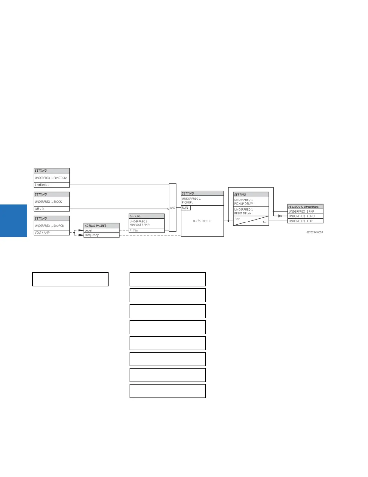
5
The steady-state frequency of a power system is a certain indicator of the existing balance between the generated power
and the load. Whenever this balance is disrupted through the loss of an important generating unit or the isolation of part
of the system from the rest of the system, the effect is a reduction in frequency. If the control systems of the system
generators do not respond fast enough, the system can collapse. A reliable method to quickly restore the balance between
load and generation is to automatically disconnect selected loads, based on the actual system frequency. This technique,
called “load-shedding,” maintains system integrity and minimize widespread outages. After the frequency returns to
normal, the load can be restored automatically or manually.
UNDERFREQ 1 SOURCE — This setting is used to select the source for the signal to be measured. The element first checks for
a live phase voltage available from the selected source. If voltage is not available, the element attempts to use a phase
current. If neither voltage nor current is available, the element does not operate, as it does not measure a parameter
below the minimum voltage/current setting.
UNDERFREQ 1 MIN VOLT/AMP — Selects the minimum per unit voltage or current level required to allow the underfrequency
element to operate. This threshold is used to prevent an incorrect operation because there is no signal to measure.
UNDERFREQ 1 PICKUP — Selects the level at which the underfrequency element is to pickup. For example, if the system
frequency is 60 Hz and the load shedding is required at 59.5 Hz, the setting is 59.50 Hz.
Figure 5-161: Underfrequency logic
5.8.6 Overfrequency (ANSI 81O)
SETTINGS CONTROL ELEMENTS OVERFREQUENCY OVERFREQUENCY 1(4)
There are four overfrequency elements, numbered 1 through 4.
A frequency calculation for a given source is made on the input of a voltage or current channel, depending on which is
available. The channels are searched for the signal input in the following order: voltage channel A, auxiliary voltage
channel, current channel A, and ground current channel. The first available signal is used for frequency calculation.
OVERFREQUENCY 1
OVERFREQ 1 FUNCTION:
Disabled
Range: Disabled, Enabled
OVERFREQ 1 BLOCK:
Off
Range: FlexLogic operand
OVERFREQ 1 SOURCE:
SRC 1
Range: SRC 1, SRC 2, SRC 3, SRC 4
OVERFREQ 1 PICKUP:
60.50 Hz
Range: 20.00 to 65.00 Hz in steps of 0.01
OVERFREQ 1 PICKUP
DELAY: 0.500 s
Range: 0.000 to 65.535 s in steps of 0.001
OVERFREQ 1 RESET
DELAY : 0.500 s
Range: 0.000 to 65.535 s in steps of 0.001
OVERFREQ 1 TARGET:
Self-reset
Range: Self-reset, Latched, Disabled
OVERFREQ 1 EVENTS:
Disabled
Range: Disabled, Enabled