CHAPTER 5: SETTINGS GROUPED ELEMENTS
M60 MOTOR PROTECTION SYSTEM – INSTRUCTION MANUAL 5-225
5
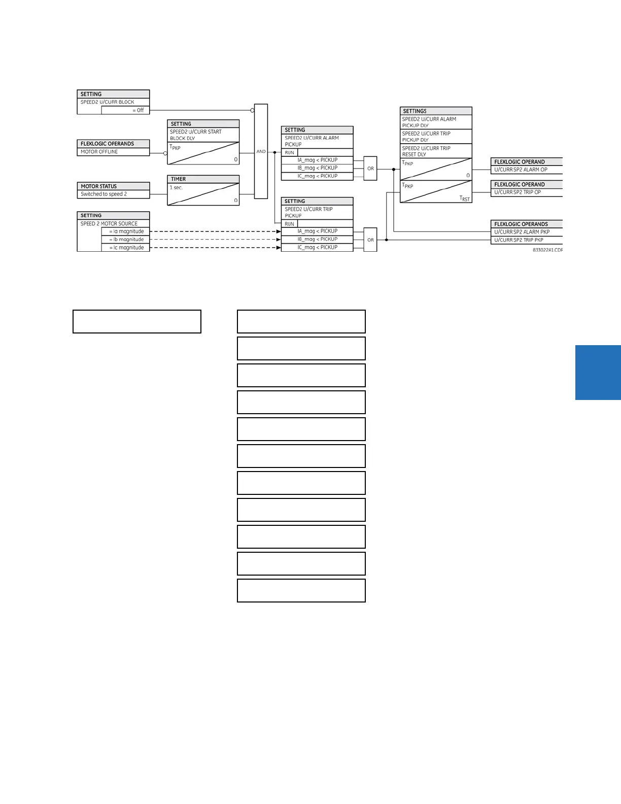
Figure 5-122: Speed 2 undercurrent logic
5.7.4 Stator differential (ANSI 87S)
SETTINGS GROUPED ELEMENTS SETTING GROUP 1(6) STATOR DIFFERENTIAL
The stator differential protection element is intended for use on the stator windings of rotating machinery.
STATOR
DIFFERENTIAL
STATOR DIFF
FUNCTION: Disabled
Range: Disabled, Enabled
STATOR DIFF LINE
END SOURCE: SRC 1
Range: SRC 1, SRC 2, SRC 3, SRC 4
STATOR DIFF NEUTRAL
END SOURCE: SRC 1
Range: SRC 1, SRC 2, SRC 3, SRC 4
STATOR DIFF
PICKUP: 0.100 pu
Range: 0.050 to 1.000 pu in steps of 0.001
STATOR DIFF
SLOPE 1: 10 %
Range: 1 to 100% in steps of 1
STATOR DIFF
BREAK 1: 1.15 pu
Range: 1.00 to 1.50 pu in steps of 0.01
STATOR DIFF
SLOPE 2: 80 %
Range: 1 to 100% in steps of 1
STATOR DIFF
BREAK 2: 8.00 pu
Range: 1.50 to 30.00 pu in steps of 0.01
STATOR DIFF
BLK: Off
Range: FlexLogic operand
STATOR DIFF
TARGET: Self-reset
Range: Self-reset, Latched, Disabled
STATOR DIFF
EVENTS: Disabled
Range: Disabled, Enabled