5-190 M60 MOTOR PROTECTION SYSTEM – INSTRUCTION MANUAL
GROUPED ELEMENTS CHAPTER 5: SETTINGS
5
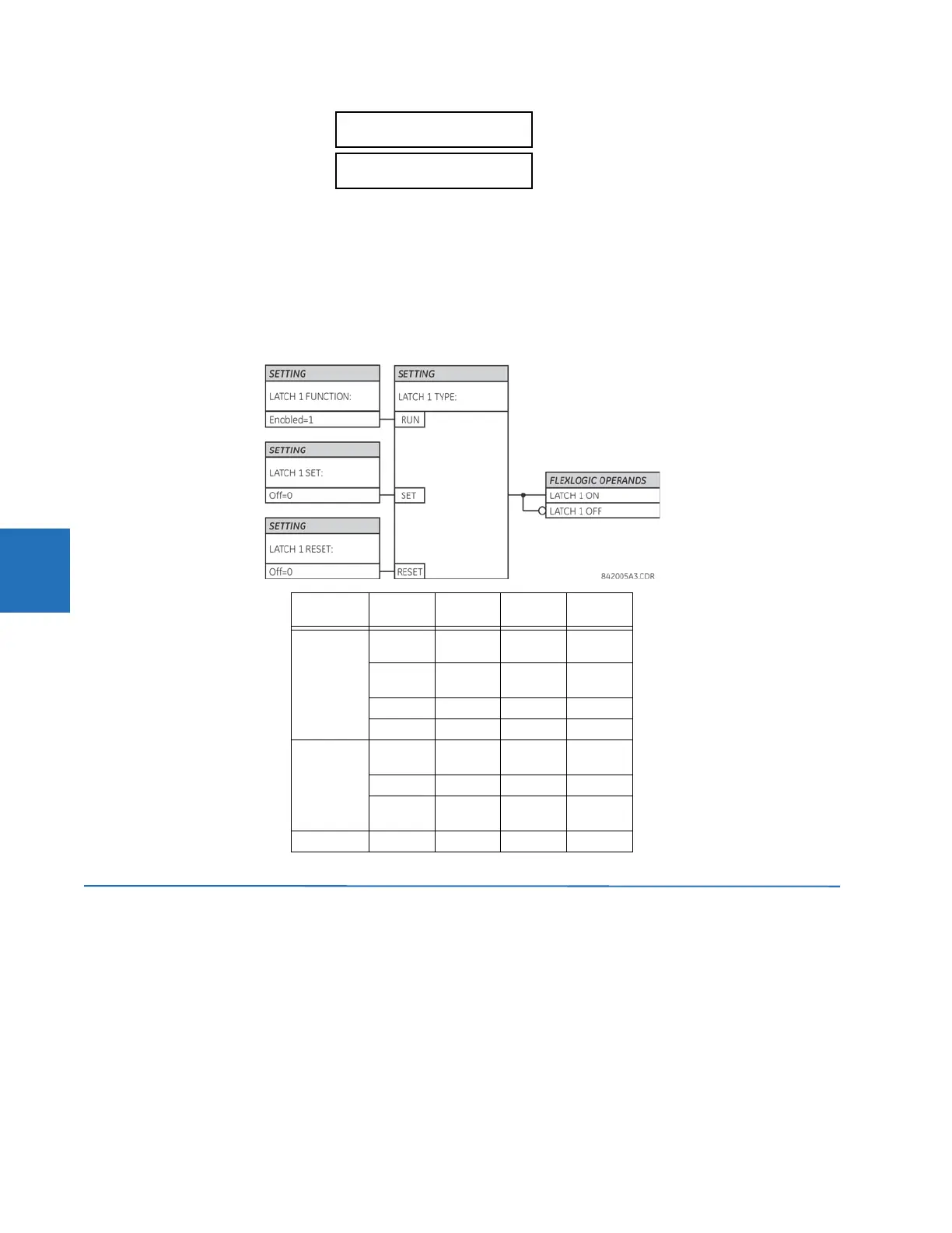
The non-volatile latches provide a permanent logical flag that is stored safely and do not reset upon restart after the relay
is powered down. Typical applications include sustaining operator commands or permanently blocking relay functions,
such as Autorecloser, until a deliberate interface action resets the latch.
LATCH 1 TYPE — This setting characterizes Latch 1 to be Set- or Reset-dominant.
LATCH 1 SET — If asserted, the specified FlexLogic operands 'sets' Latch 1.
LATCH 1 RESET — If asserted, the specified FlexLogic operand 'resets' Latch 1.
Figure 5-97: Non-volatile latch operation table (N = 1 to 16) and logic
5.7 Grouped elements
5.7.1 Overview
Each protection element can be assigned up to six sets of settings with designations 1 to 6. The performance of these
elements is defined by the active setting group at a given time. Multiple setting groups allow the user to conveniently
change protection settings for different operating situations (for example, altered power system configuration or season of
the year). The active setting group can be preset or selected in the
SETTING GROUPS menu (see the Control Elements section
later in this chapter). See also the Introduction to Elements section at the beginning of this chapter.
LATCH 1
TARGET: Self-reset
Range: Self-reset, Latched, Disabled
LATCH 1
EVENTS: Disabled
Range: Disabled, Enabled
Latch n type Latch n
set
Latch n
reset
Latch n
on
Latch n
off
Reset
Dominant
ON OFF ON OFF
OFF OFF Previous
State
Previous
State
ON ON OFF ON
OFF ON OFF ON
Set
Dominant
ON OFF ON OFF
ON ON ON OFF
OFF OFF Previous
State
Previous
State
OFF ON OFF ON