Home
GE
Protection Device
M60
Page 372
GE M60 - Page 372
676 pages
Manual
Save Page as PDF
To Next Page
To Next Page
To Previous Page
To Previous Page
Loading...
5-164
M60 MOT
OR PROTECTION SYSTEM – INSTRUCTION MANUAL
SYSTEM SETUP
CHAPTER 5: SETTINGS
5
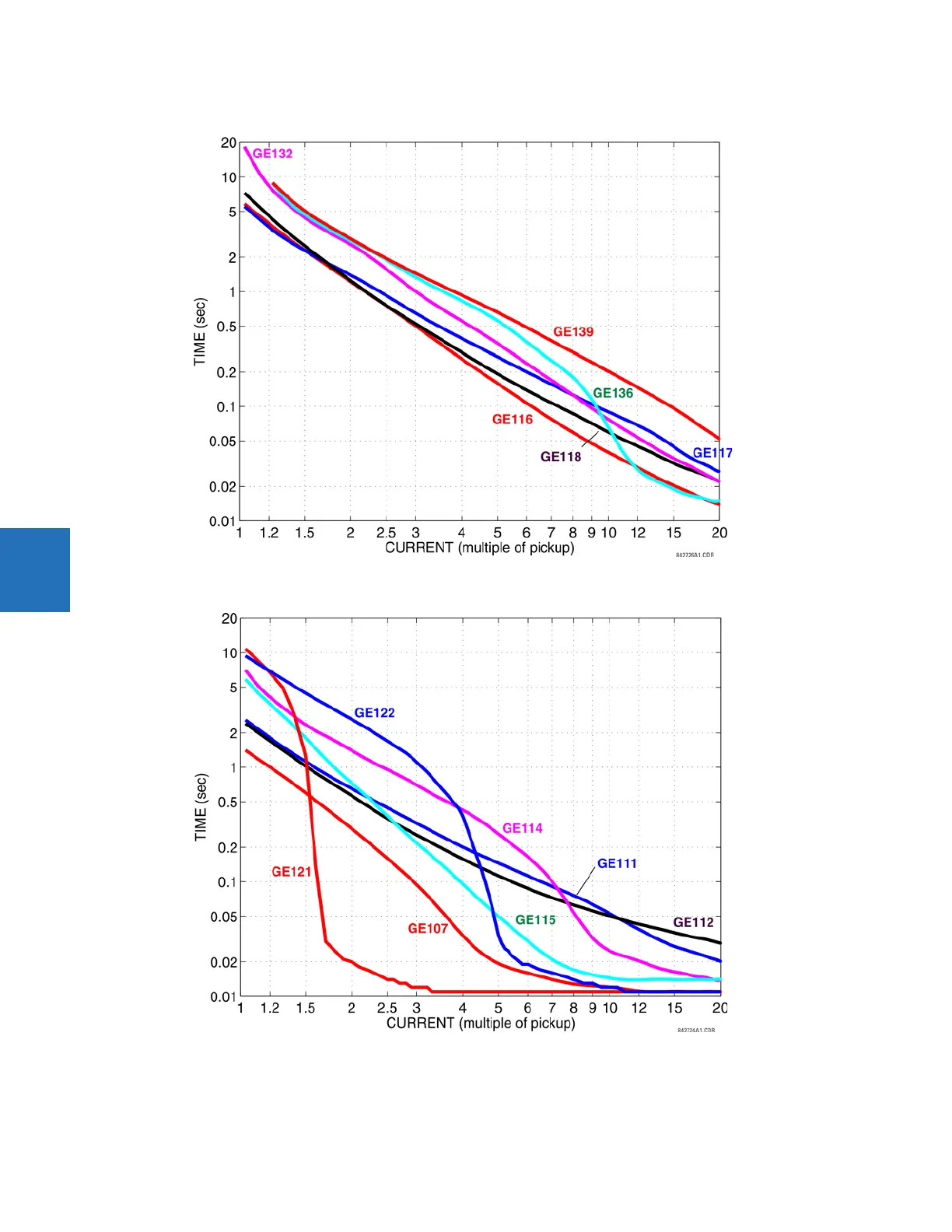
Figure 5-83: Recloser curves GE116, GE117, GE118, GE132, GE136, and GE139
Figure 5-84: Recloser curves GE107, GE
111, GE112, GE114, GE115, GE121, a
nd GE122
371
373
Table of Contents
Main Page
Default Chapter
3
Table of Contents
3
1 Introduction
11
Safety Symbols and Definitions
11
General Cautions and Warnings
11
For Further Assistance
12
2 Product Description
15
Description
16
Security
17
Order Codes
21
Order Codes with Enhanced CT/VT Modules
21
Order Codes with Process Bus Modules
26
Replacement Modules
29
Signal Processing
32
UR Signal Processing
32
Specifications
34
Protection Elements
34
User-Programmable Elements
39
Monitoring
41
Metering
42
Inputs
42
Power Supply
44
Outputs
45
Communication Protocols
47
Inter-Relay Communications
48
Cybersentry Security
49
Graphical Front Panel
49
Environmental
50
Type Tests
51
Production Tests
51
Approvals
52
Maintenance
52
3 Installation
53
Unpack and Inspect
53
Panel Cutouts
54
Horizontal Units
54
Vertical Units
57
Rear Terminal Layout
62
Wiring
64
Typical Wiring
64
Dielectric Strength
65
Control Power
65
CT/VT Modules
66
Process Bus Modules
68
Contact Inputs and Outputs
68
Transducer Inputs and Outputs
79
RS232 Port
81
CPU Communication Ports
82
Irig-B
84
Direct Input and Output Communications
85
Description
85
Fiber: LED and ELED Transmitters
88
Fiber Laser Transmitters
88
Interface
89
RS422 Interface
93
RS422 and Fiber Interface
95
And Fiber Interface
96
IEEE C37.94 Interface
96
C37.94SM Interface
99
Activate Relay
102
Install Software
103
Enervista Communication Overview
103
System Requirements
104
Install Software
105
Add Device to Software
106
Set IP Address in UR
106
Configure Serial Connection
111
Configure Ethernet Connection
112
Configure Modem Connection
114
Automatic Discovery of UR Devices
114
Connect to the M60
115
Connect to the M60 in Enervista
115
Use Quick Connect Via the Front Panel RS232 Port
116
Use Quick Connect Via a Rear Ethernet Port
117
Set up Cybersentry and Change Default Password
118
Import Settings
118
Connect to D400 Gateway
119
Oscillography Files
119
Event Records
119
Log Files
119
Setting Files
120
4 Interfaces
121
Enervista Software Interface
121
Introduction
121
Settings Files
121
Event Viewing
122
File Support
123
Enervista Main Window
123
Protection Summary Window
124
Settings Templates
125
Secure and Lock Flexlogic Equations
129
Settings File Traceability
132
Front Panel Interface
134
Front Panel
134
Front Panel Display
137
Front Panel Navigation Keys
158
LED Indicators
160
Front Panel Labelling
164
Menu Navigation
171
Change Settings
173
View Actual Values
178
Breaker Control
179
Change Passwords
180
Logic Diagrams
182
Invalid Password Entry
182
Flexlogic Design Using Engineer
183
Design Logic
185
Send File to and from Device
195
Monitor Logic
196
View Front Panel and Print Labels
197
Generate Connectivity Report
198
Preferences
198
Toolbars
202
5 Settings
209
Settings Menu
209
Overview
212
Introduction to Elements
212
Introduction to AC Sources
213
Product Setup
215
Security
215
Display Properties
233
Graphical Front Panel
235
Clear Relay Records
247
Communications
248
Modbus User Map
316
Real-Time Clock
317
User-Programmable Fault Report
321
Oscillography
322
Data Logger
324
User-Programmable Leds
326
User-Programmable Self-Tests
330
Control Pushbuttons
330
User-Programmable Pushbuttons
332
Flexstate Parameters
337
User-Definable Displays
338
Direct Inputs and Outputs
340
Teleprotection
346
Remote Resources
347
Remote Resources Configuration
347
AC Inputs
349
System Setup
349
Power System
350
Signal Sources
351
Motor
354
Breakers
356
Disconnect Switch Control
361
Flexcurves
366
Flexlogic
373
Flexlogic Operands
373
Flexlogic Rules
386
Flexlogic Evaluation
387
Flexlogic Example
387
Flexlogic Equation Editor
392
Flexlogic Timers
392
Flexelements
392
Non-Volatile Latches
397
Grouped Elements
398
Overview
398
Setting Group 1
399
Motor
399
Stator Differential (ANSI 87S)
433
Power
437
Phase Current
442
Neutral Current
454
Ground Current
462
Breaker Failure (ANSI 50BF)
470
Voltage Elements
480
Control Elements
487
Overview
487
Trip Bus
487
Setting Groups
489
Selector Switch
490
Underfrequency (ANSI 81U)
497
Overfrequency (ANSI 81O)
498
Motor Start Supervision
499
Reduced Voltage Starting
502
Digital Elements
504
Digital Counters
507
Monitoring Elements
509
Inputs/Outputs
526
Contact Inputs
526
Virtual Inputs
528
Contact Outputs
529
Virtual Outputs
532
Resetting
532
Direct Inputs and Outputs
533
Teleprotection
537
Transducer Inputs/Outputs
539
Dcma Inputs
539
RTD Inputs
540
RRTD Inputs
542
Dcma Outputs
545
Testing
549
Test Mode Function
549
Test Mode Forcing
550
Force Contact Inputs
550
Force Contact Outputs
551
6 Actual Values
553
Actual Values Menu
553
Front Panel
555
Status
556
Motor
556
Contact Inputs
556
Virtual Inputs
557
Rxgoose Boolean Inputs
557
Rxgoose DPS Inputs
557
Teleprotection Inputs
557
Contact Outputs
558
Virtual Outputs
558
Rxgoose Status
558
Rxgoose Statistics
559
Digital Counters
559
Selector Switches
559
Flexstates
560
Ethernet
560
Real Time Clock Synchronizing
560
Direct Inputs
561
Direct Devices Status
562
EGD Protocol Status
562
Teleprotection Channel Tests
562
Remaining Connection Status
563
Parallel Redundancy Protocol (PRP)
563
Txgoose Status
564
Metering
564
Metering Conventions
564
Stator Differential
568
Motor
568
Sources
568
Sensitive Directional Power
572
Broken Rotor Bar
572
Tracking Frequency
573
Flexelements
573
Rxgoose Analogs
574
Transducer Inputs and Outputs
575
Records
575
User-Programmable Fault Reports
575
Starting Records
575
Motor Learned Data
576
Event Records
578
Oscillography
579
Data Logger
579
Breaker Maintenance
580
Product Information
581
Model Information
581
Firmware Revisions
581
7 Commands and Targets
583
Commands Menu
583
Virtual Inputs
584
Clear Records
584
Set Date and Time
585
Relay Maintenance
585
Security
586
Targets Menu
587
Target Messages
587
Relay Self-Tests
588
8 Commissioning
597
Testing
597
Testing Underfrequency and Overfrequency Elements
597
9 Theory of Operation
599
Saturation Detector
599
CT Saturation Detection
599
10 Maintenance
603
Devices with Site Targets
603
Data with Modbus Analyzer
603
Monitoring
603
General Maintenance
605
In-Service Maintenance
605
Out-Of-Service Maintenance
605
Retrieve Files
605
Unscheduled Maintenance (System Interruption)
605
Convert Device Settings
607
Compare Settings
609
Compare against Defaults
609
Back up and Restore Settings
610
Copy Settings to Other Device
609
Back up Settings
610
Restore Settings
613
Upgrade Firmware
615
Upgrade Software
615
Replace Front Panel
617
Replace Module
625
Battery
626
Replace Battery for SH/SL Power Supply
626
Dispose of Battery
628
Clear Files and Data after Uninstall
631
Repairs
631
Disposal
632
Storage
632
A.1 Flexanalog Items
633
Flexanalog Items
633
B Radius Server
645
RADIUS Server Configuration
645
C Command Line
647
Command Line Interface
647
D.1 Warranty
653
Warranty
653
Revision History
653
Related product manuals
GE M60 UR Series
662 pages
GE MI-869
552 pages
GE Multilin 850
616 pages
GE Multilin g60
722 pages
GE Multilin W650
622 pages
GE MiCOM P747 Agile
458 pages
GE Multilin 3 Series
74 pages
GE Feeder Management Relay 750
346 pages
GE F60
732 pages
GE 850
664 pages
GE 869
606 pages
GE P444
622 pages