CHAPTER 5: SETTINGS GROUPED ELEMENTS
M60 MOTOR PROTECTION SYSTEM – INSTRUCTION MANUAL 5-193
5
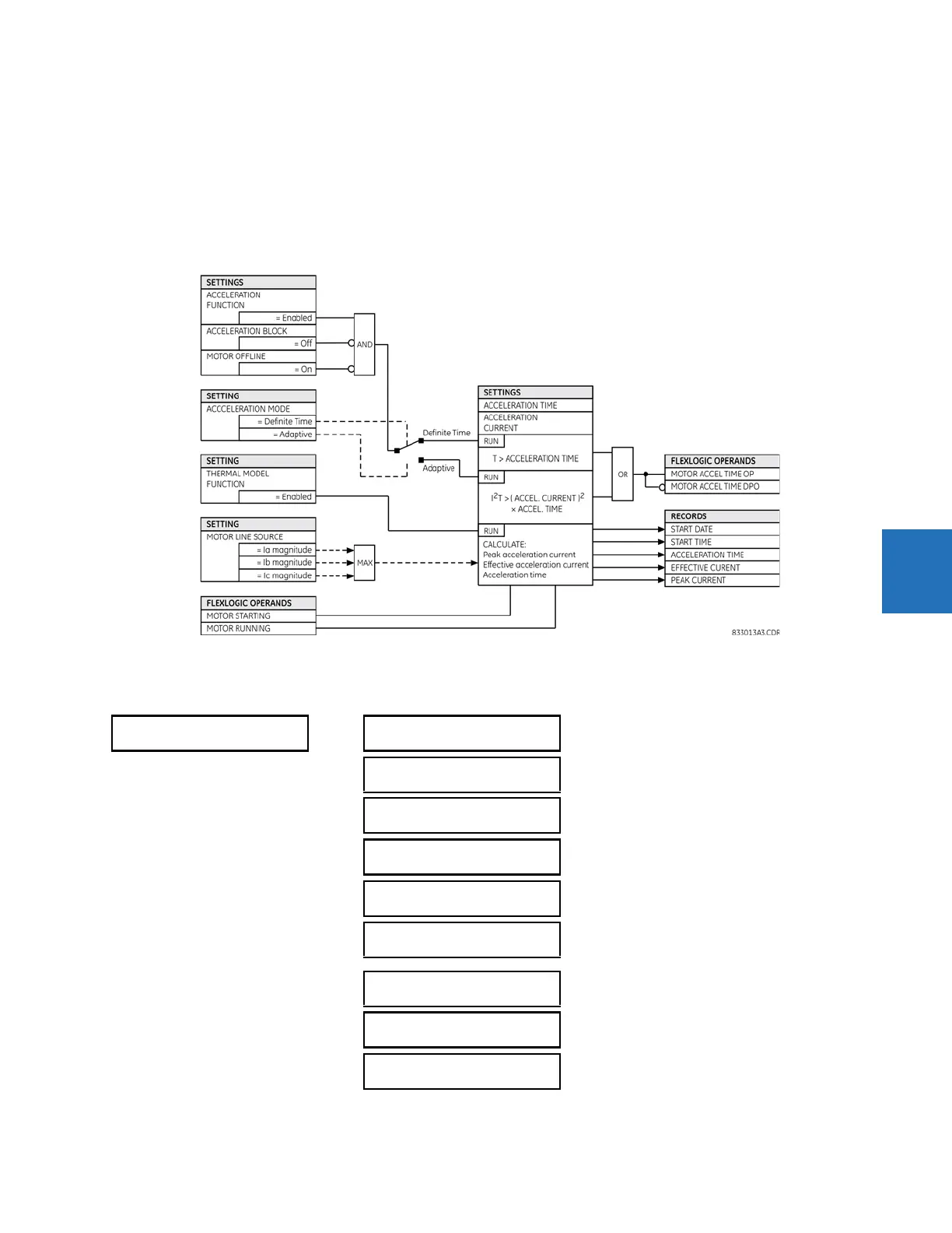
ACCELERATION MODE — This setting defines the operating mode of the acceleration time element. When set to “Definite
Time,” the element times duration of the motor start and operates when the starting time exceeds the
ACCELERATION TIME
setting. When set to “Adaptive,” the element uses the effective accelerating current to adapt to the starting conditions. The
operating equation assumes that the accelerating power is proportional to the square of the current and neglects any
current unbalance or impact of the rotor slip. Consequently, in the adaptive mode, the element operates when the square
of the current integrated from the beginning of the start up to a given time exceeds
(Acceleration Current)
2
x Acceleration Time.
Figure 5-99: Acceleration time logic
5.7.3.3 Thermal model
SETTINGS GROUPED ELEMENTS SETTING GROUP 1(6) MOTOR THERMAL MODEL
THERMAL MODEL
THERMAL MODEL
FUNCTION: Disabled
Range: Disabled, Enabled
THERMAL MODEL
CURVE: Motor
Range: Motor, Flexcurve A, Flexcurve B, Flexcurve C,
Flexcurve D, IEC
THERMAL MODEL CURVE
EFFECT: Cutoff
Range: Cutoff, Shift
IEC CURVE k FACTOR:
1.10
Range: 1.00 to 1.50 in steps of 0.05
IEC CURVE TIME
CONSTANT: 45 min.
Range: 0 to 1000 min. in steps of 1
THERMAL MODEL
TD MULTIPLIER: 1.00
Range: 0.00 to 16.00 in steps of 0.01 when thermal
model curve is Motor, otherwise 0.00 to 600.00 in steps
of 0.01
UNBALANCE BIAS
K FACTOR: 0
Range: 0 to 19 in steps of 1
COOL TIME CONSTANT
RUNNING: 15 min.
Range: 1 to 65000 min. in steps of 1
COOL TIME CONSTANT
STOPPED: 30 min.
Range: 1 to 65000 min. in steps of 1