CHAPTER 5: SETTINGS GROUPED ELEMENTS
M60 MOTOR PROTECTION SYSTEM – INSTRUCTION MANUAL 5-197
5
t = time to trip
= IEC time constant defined by IEC CURVE TIME CONSTANT setting
I = measured motor load current
I
p
= Motor load current before overload occurs
k = k-factor (overload factor) defined by
IEC CURVE k FACTOR setting applied to I
b
I
b
= Motor rated current specified by the MOTOR FULL LOAD AMPS setting
THERMAL MODEL CURVE EFFECT — This setting affects the time-to-trip thermal curves when the THERMAL MODEL CURVE is
selected as “Motor.” This setting takes into account the design of the machine with respect to overload capability as
determined by the overload (service) factor. For motor designs where temperature rise above ambient is based on full load
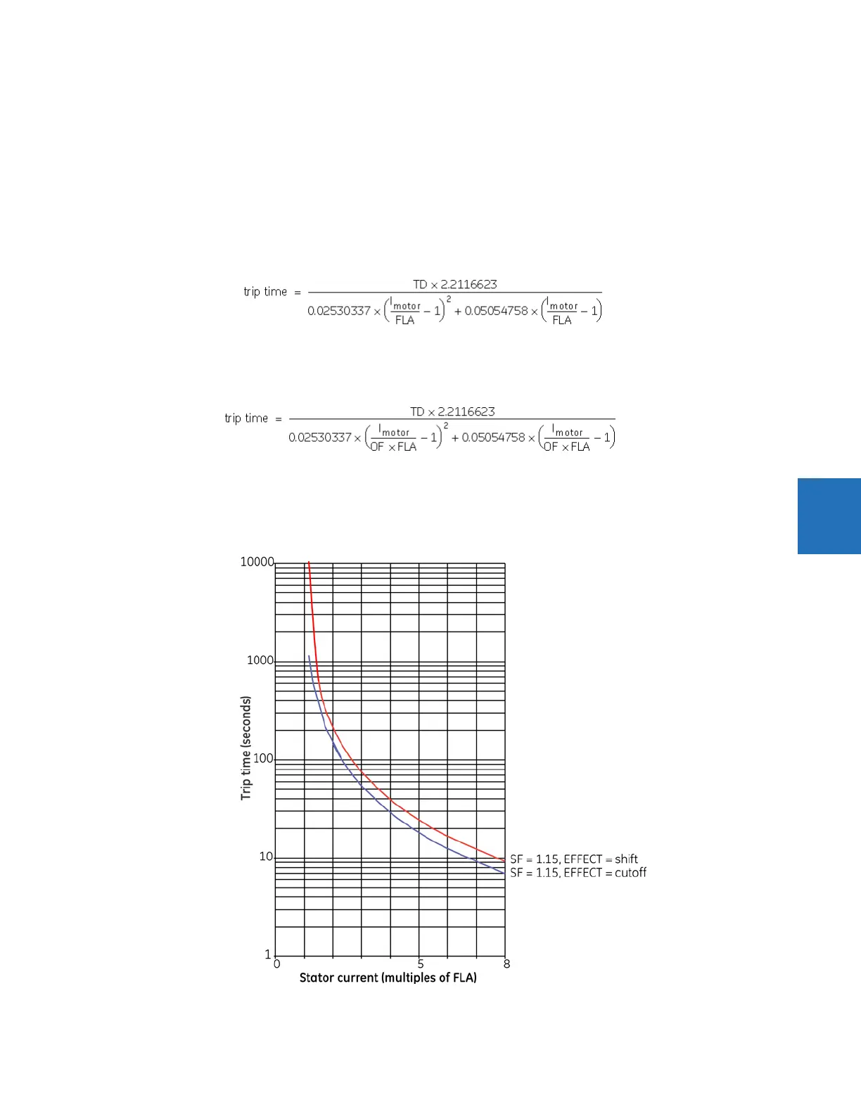
current, select this setting as “Cutoff.” The time to trip is then calculated using the following equation.
Eq. 5-10
In the equation, the motor stator current (I
motor
) and motor rated current (FLA) are expressed in per units of relay current.
For specialized motor designs where temperature rise above ambient is based on the product of the service factor and full
load current (OF × FLA), select “Shifted” for this setting. The time to trip is then calculated using the following equation.
Eq. 5-11
In the equation, the motor stator current (I
motor
) and motor rated current (FLA) are expressed in per units of relay current.
In case of uncertainty, use the more conservative “Cutoff” value.
The following figure illustrates the impact of this setting on the time to trip thermal curves.
Figure 5-100: Impact of the thermal model curve effect setting