5-220 M60 MOTOR PROTECTION SYSTEM – INSTRUCTION MANUAL
GROUPED ELEMENTS CHAPTER 5: SETTINGS
5
5.7.3.6 Undercurrent (ANSI 37)
SETTINGS GROUPED ELEMENTS SETTING GROUP 1(6) MOTOR UNDERCURRENT
The undercurrent function uses the source defined by the
SYSTEM SETUP MOTOR MOTOR LINE SOURCE setting. Phase
currents must be configured on this source; otherwise, the undercurrent function is not operational. The element responds
to a per-phase current.
If the undercurrent function is enabled, a trip or alarm is initiated once the IA, IB, or IC current magnitude falls below the
pickup level for a time specified by the delay setting. For example, the undercurrent element can be used to detect loss-of-
load conditions. This can be especially useful for detecting process related problems.
The undercurrent element is active when the motor is running at speed 1, that is, when the motor status is running and
speed 2 is not employed or active.
UNDERCURRENT START BLOCK DLY — This setting specifies the length of time to block the undercurrent function when motor
is starting. If not in the starting state, the motor status is indicated by the MOTOR OFFLINE operand. See the Motor section
under
SETTINGS SYSTEM SETUP MOTOR for information on using the MOTOR OFFLINE operand for state determination.
The undercurrent element is active only when the motor is running and is blocked upon the initiation of a motor start for a
period of time specified by this setting. For example, this block delay can be used to allow pumps to build up head before
the undercurrent element trips or alarms. A value of 0 specifies that the feature is not blocked from start. For values other
than 0, the feature is disabled when the motor is stopped and also from the time a start is detected until the time entered
expires.
UNDERCURRENT ALARM PICKUP — This setting specifies a pickup threshold for the alarm stage. Set the alarm pickup
threshold less than the motor load current during normal operations.
UNDERCURRENT ALARM PICKUP DLY — This setting specifies a time delay for the alarm stage. Set the time delay long enough
to overcome any short lowering of the current (for example, during system faults).
UNDERCURRENT TRIP PICKUP — This setting specifies a pickup threshold for the trip stage. Set the pickup less than the
corresponding setting for the alarm stage.
UNDERCURRENT TRIP PICKUP DLY — This setting specifies a time delay for the trip stage. Set the time delay long enough to
overcome any short lowering of the current (for example, during system faults).
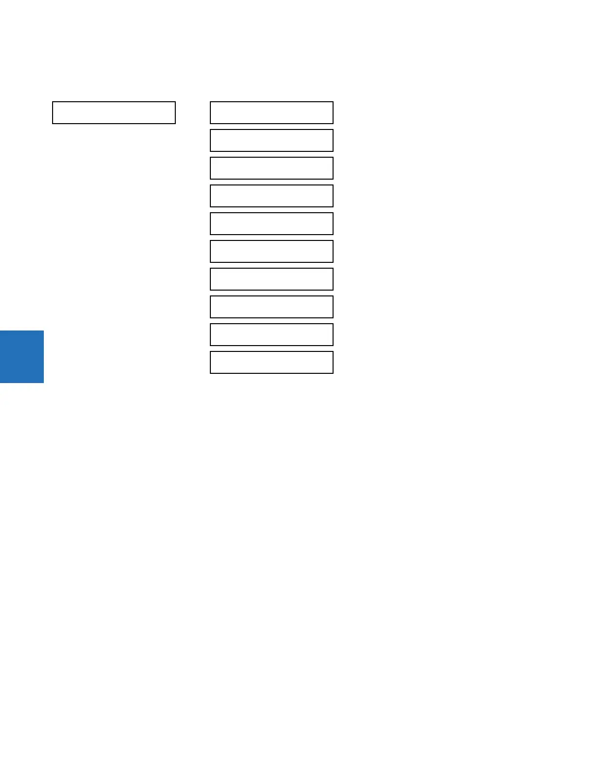
UNDERCURRENT
UNDERCURRENT
FUNCTION: Disabled
Range: Disabled, Enabled
UNDERCURRENT START
BLOCK DLY: 0.50 s
Range: 0.00 to 600.00 s in steps of 0.01
UNDERCURRENT ALARM
PICKUP: 0.70 x FLA
Range: 0.10 to 0.95 × FLA in steps of 0.01
UNDERCURRENT ALARM
PICKUP DLY: 2.00 s
Range: 0.00 to 600.00 s in steps of 0.01
UNDERCURRENT TRIP
PICKUP: 0.70 x FLA
Range: 0.10 to 0.95 × FLA in steps of 0.01
UNDERCURRENT TRIP
PICKUP DLY: 1.00 s
Range: 0.00 to 600.00 s in steps of 0.01
UNDERCURRENT TRIP
RESET DLY: 1.00 s
Range: 0.00 to 600.00 s in steps of 0.01
UNDERCURRENT BLOCK:
Off
Range: FlexLogic operand
UNDERCURRENT TARGET:
Self-reset
Range: Self-reset, Latched, Disabled
UNDERCURRENT EVENTS:
Disabled
Range: Disabled, Enabled