5-222 M60 MOTOR PROTECTION SYSTEM – INSTRUCTION MANUAL
GROUPED ELEMENTS CHAPTER 5: SETTINGS
5
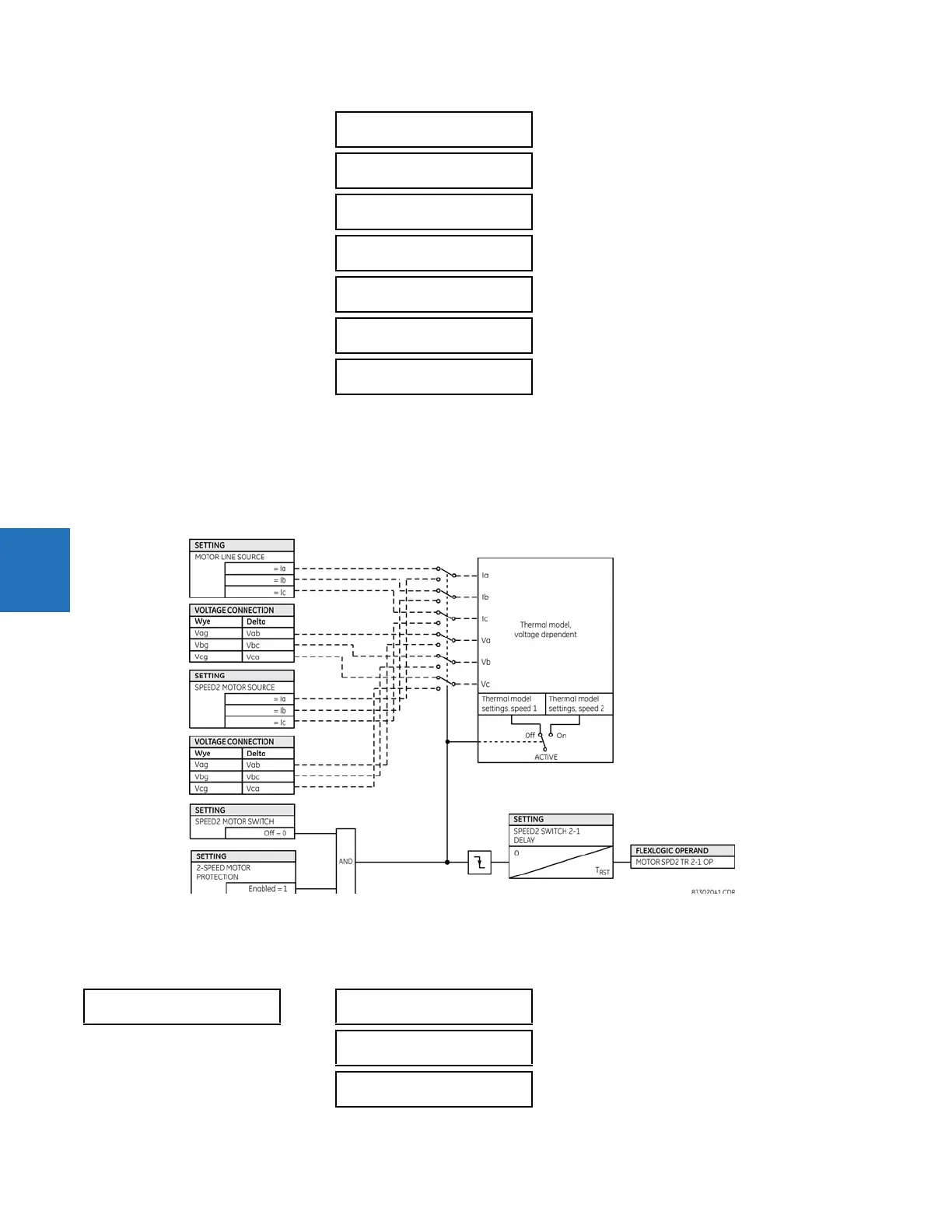
When two-speed motor functionality is used, these settings allow the selection of proper parameters for the thermal
model when the motor is switched to the second speed. There is one thermal model in the M60, and it has inputs for
overload conditions from calculations at both speeds. As such, the accumulated thermal capacity is calculated from
overload contributions at each speed.
See the Thermal Model section earlier for details on settings for the thermal model at the second motor speed.
Figure 5-120: Two-speed motor thermal model logic
5.7.3.9 Two-speed motor acceleration time
SETTINGS GROUPED ELEMENTS SETTING GROUP 1(6) MOTOR TWO-SPEED MOTOR SPEED2
ACCELERATION TIME
SPEED2 VD VOLT LOSS:
Off
Range: FlexLogic operand
SPEED2 VD STALL CURR
@ MIN V: 4.50 x FLA
Range: 1.50 to 20.00 x FLA in steps of 0.01
SPEED2 VD SAFE STALL
TIME @ MIN V: 20.0 s
Range: 0.1 to 1000.0 s in steps of 0.1
SPEED2 VD ACCL INSCT
@ MIN V: 4.00 x FLA
Range: 1.50 to 20.00 x FLA in steps of 0.01
SPEED2 VD STALL CURR
@ 100%V: 6.00 x FLA
Range: 1.50 to 20.00 x FLA in steps of 0.01
SPEED2 VD SAFE STALL
TIME @ 100%V: 20.0 s
Range: 0.1 to 1000.0 s in steps of 0.1
SPEED2 VD ACCL INSCT
@ 100%V: 5.00 x FLA
Range: 1.50 to 20.00 x FLA in steps of 0.01
SPEED2
ACCELERATION TIME
SPEED2 ACCELERATION
CURRENT: 6.00 x FLC
Range: 1.00 to 10.00 x FLC in steps of 0.01
SPEED2 ACCELERATION
TIME: 10.00 s
Range: 0.05 to 180.00 s in steps of 0.01
SPEED2 ACCEL MODE:
Definite Time
Range: Definite Time, Adaptive