CHAPTER 5: SETTINGS GROUPED ELEMENTS
M60 MOTOR PROTECTION SYSTEM – INSTRUCTION MANUAL 5-235
5
A time dial multiplier setting allows selection of a multiple of the base curve shape (where the time dial multiplier = 1) with
the curve shape (
CURVE) setting. Unlike the electromechanical time dial equivalent, operate times are directly proportional
to the time multiplier (TD MULTIPLIER) setting value. For example, all times for a multiplier of 10 are 10 times the multiplier 1
or base curve values. Setting the multiplier to zero results in an instantaneous response to all current levels above pickup.
Time overcurrent time calculations are made with an internal energy capacity memory variable. When this variable
indicates that the energy capacity has reached 100%, a time overcurrent element operates. If less than 100% energy
capacity is accumulated in this variable and the current falls below the dropout threshold of 97 to 98% of the pickup value,
the variable must be reduced. Two methods of this resetting operation are available: “Instantaneous” and “Timed.” The
“Instantaneous” selection is intended for applications with other relays, such as most static relays, which set the energy
capacity directly to zero when the current falls below the reset threshold. The “Timed” selection can be used where the
relay must coordinate with electromechanical relays.
IEEE curves
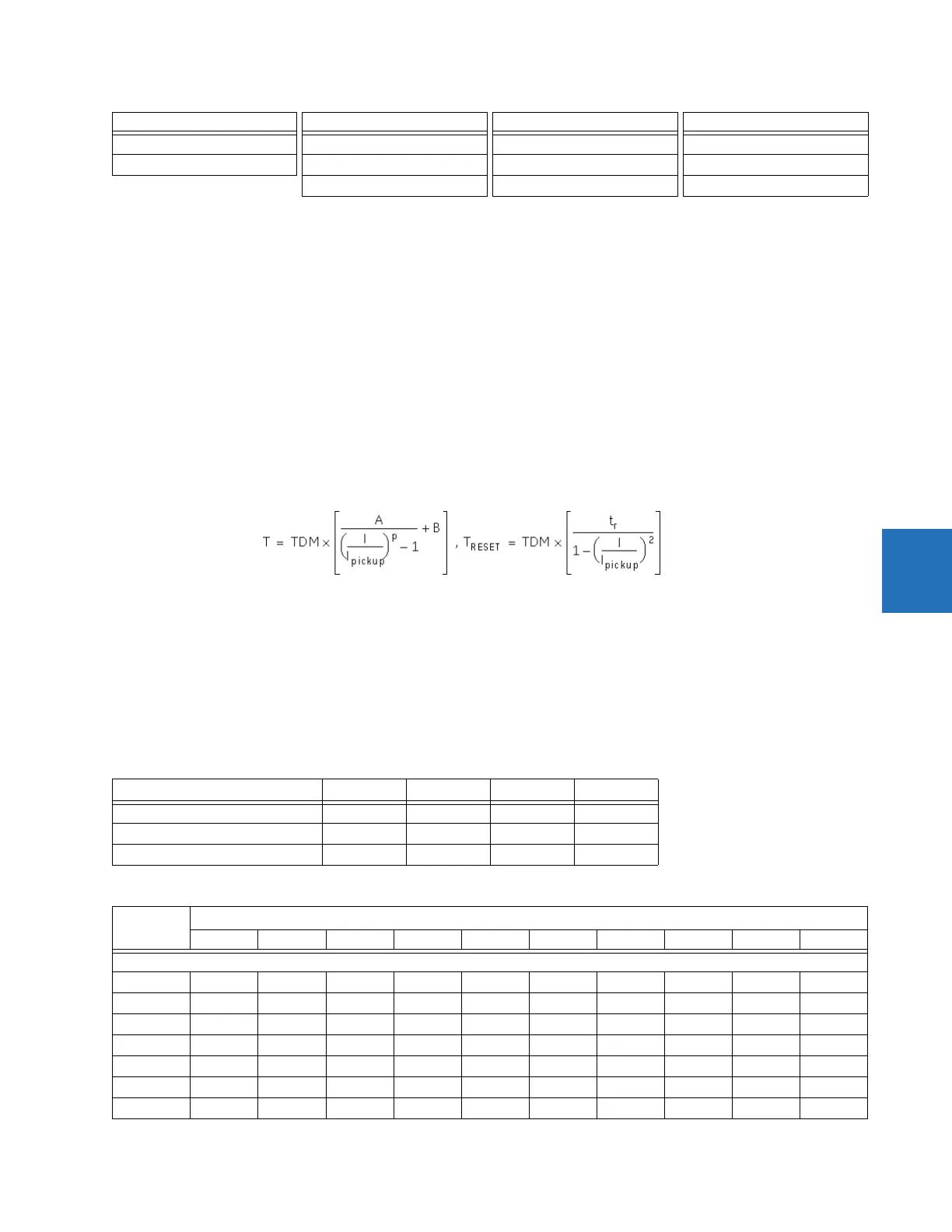
The IEEE time overcurrent curve shapes conform to industry standards and the IEEE C37.112-1996 curve classifications for
extremely, very, and moderately inverse curves. The IEEE curves are derived from the operate and reset time equations.
Eq. 5-29
where
T = operate time (in seconds)
TDM = Multiplier setting
I = input current
I
pickup
= Pickup Current setting
A, B, p = constants defined in the table
T
RESET
= reset time in seconds (assuming energy capacity is 100% and RESET is “Timed”)
t
r
= characteristic constant defined in the table
Table 5-26: IEEE inverse time curve constants
Table 5-27: IEEE curve trip times (in seconds)
IEEE Very Inverse IEC Curve B (BS142) IAC Very Inverse FlexCurves A, B, C, and D
IEEE Moderately Inverse IEC Curve C (BS142) IAC Inverse Recloser Curves
IEC Short Inverse IAC Short Inverse Definite Time
IEEE curve shape A B p t
r
IEEE Extremely Inverse 28.2 0.1217 2.0000 29.1
IEEE Very Inverse 19.61 0.491 2.0000 21.6
IEEE Moderately Inverse 0.0515 0.1140 0.02000 4.85
Multiplier
(TDM)
Current ( I / I
pickup
)
1.5 2.0 3.0 4.0 5.0 6.0 7.0 8.0 9.0 10.0
IEEE Extremely Inverse
0.5 11.341 4.761 1.823 1.001 0.648 0.464 0.355 0.285 0.237 0.203
1.0 22.682 9.522 3.647 2.002 1.297 0.927 0.709 0.569 0.474 0.407
2.0 45.363 19.043 7.293 4.003 2.593 1.855 1.418 1.139 0.948 0.813
4.0 90.727 38.087 14.587 8.007 5.187 3.710 2.837 2.277 1.897 1.626
6.0 136.090 57.130 21.880 12.010 7.780 5.564 4.255 3.416 2.845 2.439
8.0 181.454 76.174 29.174 16.014 10.374 7.419 5.674 4.555 3.794 3.252
10.0 226.817 95.217 36.467 20.017 12.967 9.274 7.092 5.693 4.742 4.065
IEEE IEC GE type IAC Other