CHAPTER 5: SETTINGS GROUPED ELEMENTS
M60 MOTOR PROTECTION SYSTEM – INSTRUCTION MANUAL 5-239
5
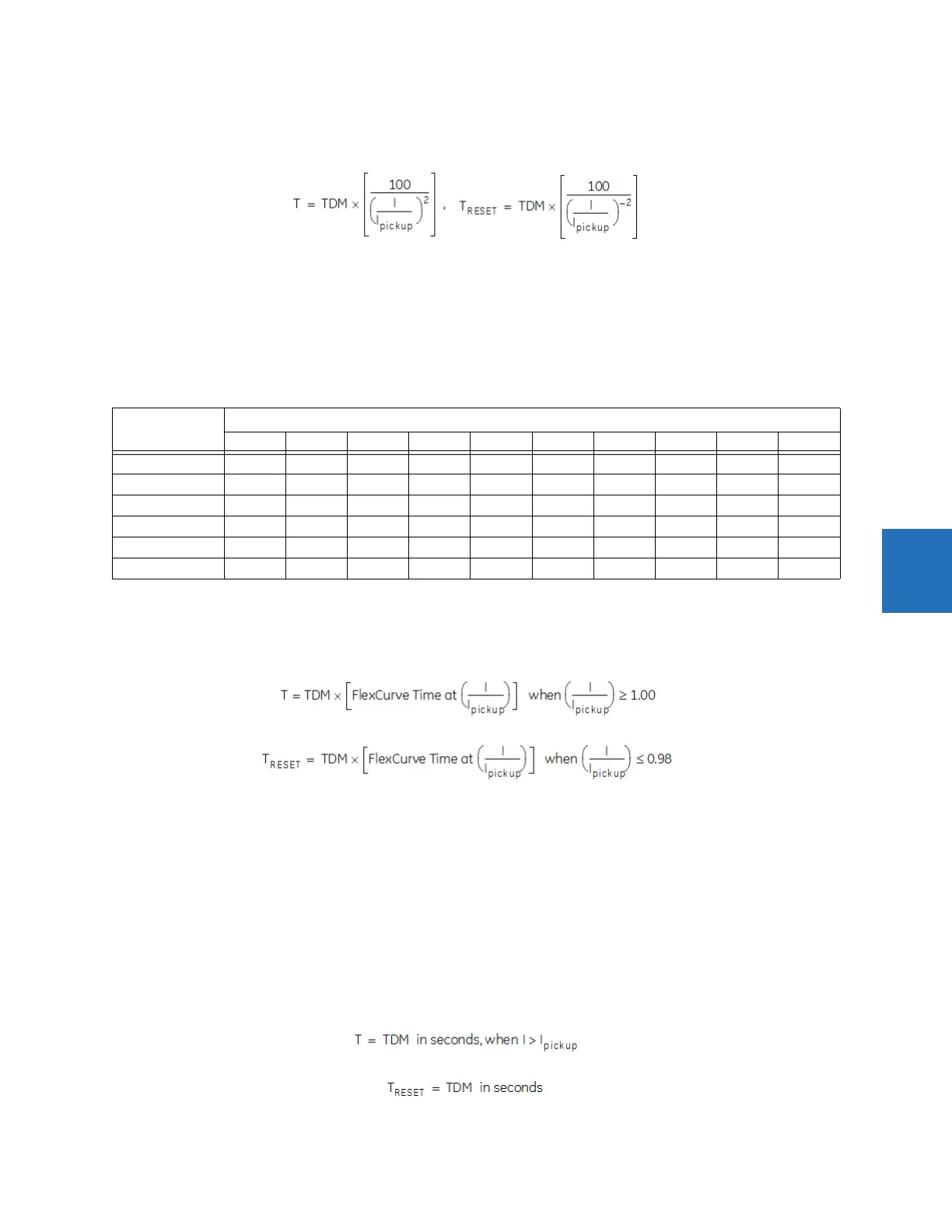
I
2
t curves
The I
2
t curves are derived as follows:
Eq. 5-32
where
T = Operate time (in seconds)
TDM = Multiplier setting
I = Input current
I
pickup
= Pickup Current setting
T
RESET
= reset time in seconds (assuming energy capacity is 100% and RESET is “Timed”)
Table 5-32: I
2
t curve trip times
FlexCurves
FlexCurves are described in the FlexCurves section later in this chapter. The curve shapes for the FlexCurves are derived
from the formulae:
Eq. 5-33
Eq. 5-34
where
T = operate time (in seconds)
TDM = Multiplier setting
I = Input Current
I
pickup
= Pickup Current setting
T
RESET
= Reset Time in seconds (assuming energy capacity is 100% and RESET: Timed)
Definite time curve
The Definite Time curve shape operates as soon as the pickup level is exceeded for a specified period of time. The base
definite time curve delay is in seconds. The curve multiplier of 0.00 to 600.00 makes this delay adjustable from
instantaneous to 600.00 seconds in steps of 10 ms. The definite time curve shapes are defined as follows:
Eq. 5-35
Eq. 5-36
Multiplier
(TDM)
Current ( I / I
pickup
)
1.5 2.0 3.0 4.0 5.0 6.0 7.0 8.0 9.0 10.0
0.01 0.44 0.25 0.11 0.06 0.04 0.03 0.02 0.02 0.01 0.01
0.10 4.44 2.50 1.11 0.63 0.40 0.28 0.20 0.16 0.12 0.10
1.00 44.44 25.00 11.11 6.25 4.00 2.78 2.04 1.56 1.23 1.00
10.00 444.44 250.00 111.11 62.50 40.00 27.78 20.41 15.63 12.35 10.00
100.00 4444.4 2500.0 1111.1 625.00 400.00 277.78 204.08 156.25 123.46 100.00
600.00 26666.7 15000.0 6666.7 3750.0 2400.0 1666.7 1224.5 937.50 740.74 600.00