2-32 M60 MOTOR PROTECTION SYSTEM – INSTRUCTION MANUAL
SPECIFICATIONS CHAPTER 2: PRODUCT DESCRIPTION
2
Break (DC inductive, L/R = 40 ms):
Operate time: < 8 ms
Contact material: silver alloy
FAST FORM-C RELAY
Make and carry: 0.1 A max. (resistive load)
Minimum load impedance:
Operate time: < 0.6 ms
Internal Limiting Resistor: 100 Ω, 2 W
SOLID-STATE OUTPUT RELAY
Operate and release time: <100 µs
Maximum voltage: 265 V DC
Maximum leakage current in off state
(excluding voltage monitor circuit current): 100 µA
Maximum continuous current: 5 A at 45°C; 4 A at 65°C
Make and carry:
for 0.2 s: 30 A as per ANSI C37.90
for 0.03 s: 300 A
Breaking capacity:
CONTROL POWER EXTERNAL OUTPUT (For dry contact input)
Capacity: 100 mA DC at 48 V DC
Isolation: ±300 Vpk
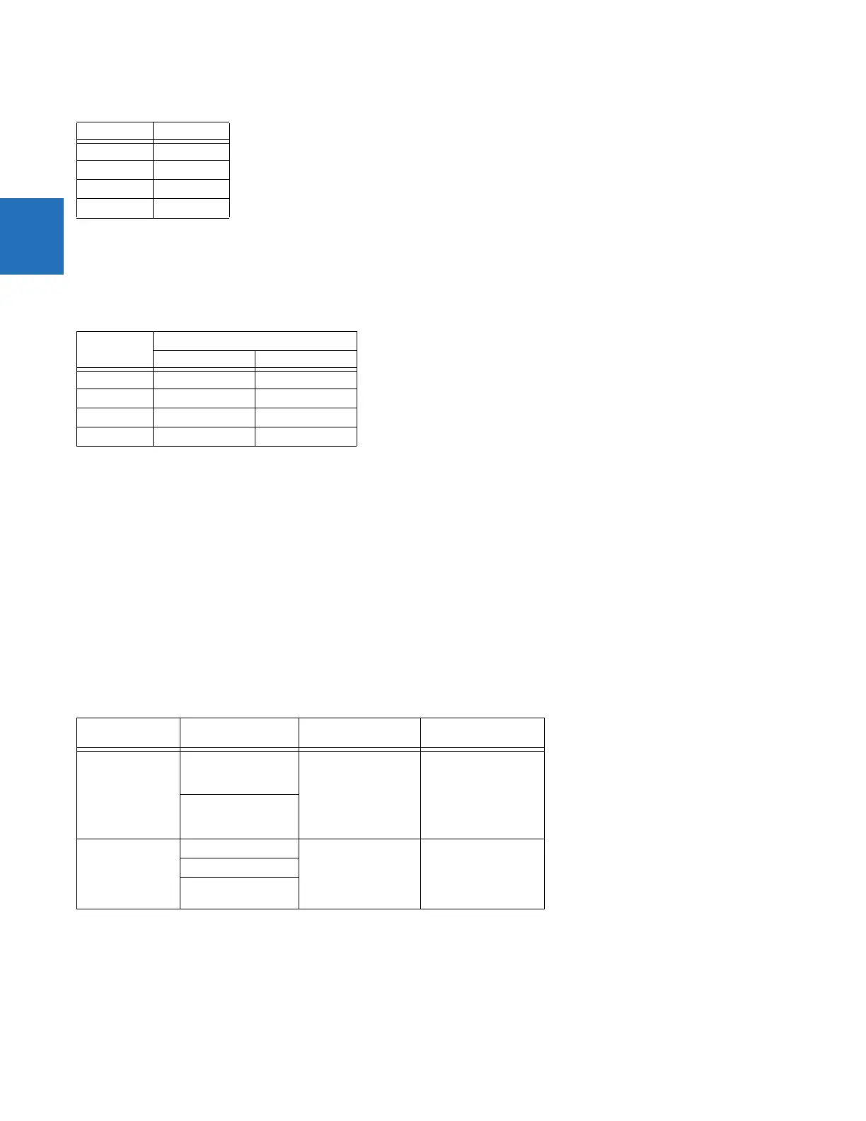
DIRECT OUTPUTS
Output points: 32
Voltage Current
24 V 1 A
48 V 0.5 A
125 V 0.3 A
250 V 0.2 A
Input voltage Impedance
2 W Resistor 1 W Resistor
250 V DC 20 KΩ 50 KΩ
120 V DC 5 KΩ 2 KΩ
48 V DC 2 KΩ 2 KΩ
24 V DC 2 KΩ 2 KΩ
Note: values for 24 V and 48 V are the same due to a
required 95% voltage drop across the load
impedance.
Specification UL 508 Utility application
(autoreclose scheme)
Industrial application
Operations per
interval
5000 operations,
1 second on,
9 seconds off
5 operations
0.2 seconds on
0.2 seconds off
within 1 minute
10000 operations
0.2 seconds on
30 seconds off
1000 operations
0.5 seconds on,
0.5 seconds off
Break capability
(0 to 250 V DC)
3.2 A at L/R = 10 ms 10 A at L/R = 40 ms 10 A at L/R = 40 ms
1.6 A at L/R = 20 ms
0.8 A
L/R =40ms