CHAPTER 5: SETTINGS GROUPED ELEMENTS
M60 MOTOR PROTECTION SYSTEM – INSTRUCTION MANUAL 5-265
5
Both current detectors provide a fast operating time for currents at small multiples of the pickup value. The overcurrent
detectors are required to operate after the breaker failure delay interval to eliminate the need for very fast resetting
overcurrent detectors.
Timer 3 logic (slow path) is supervised by a breaker auxiliary contact and a control switch contact used to indicate that the
breaker is in or out-of-service, disabling this path when the breaker is out-of-service for maintenance. There is no current
level check in this logic as it is intended to detect low magnitude faults and it is therefore the slowest to operate.
Output
The outputs from the schemes are:
• FlexLogic operands that report on the operation of portions of the scheme
• FlexLogic operand used to re-trip the protected breaker
• FlexLogic operands that initiate tripping required to clear the faulted zone. The trip output can be sealed-in for an
adjustable period.
• Target message indicating a failed breaker has been declared
• Illumination of the front panel Trip LED (and the Phase A, B, or C LED, if applicable)
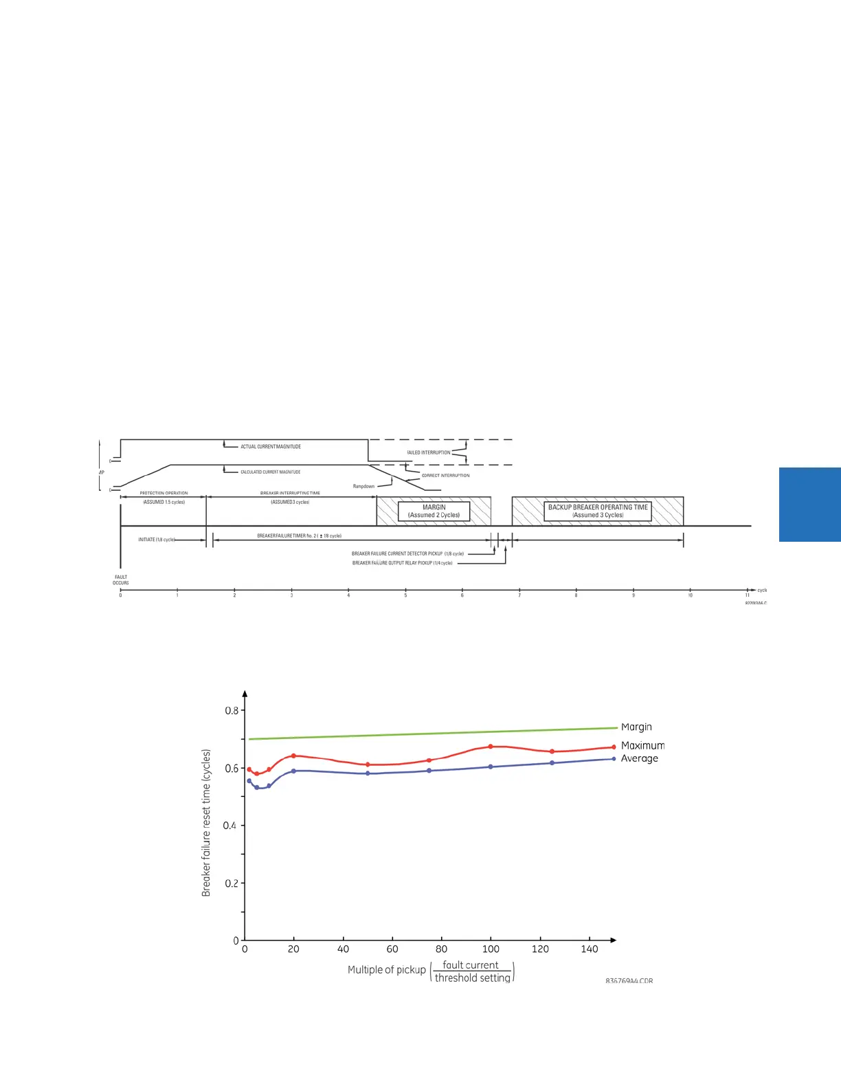
Main path sequence
Figure 5-142: Breaker failure main path sequence
The current supervision elements reset in less than 0.7 of a power cycle for any multiple of pickup current as shown in the
following figure.
Figure 5-143: Breaker failure overcurrent supervision reset time