CHAPTER 5: SETTINGS CONTROL ELEMENTS
M60 MOTOR PROTECTION SYSTEM – INSTRUCTION MANUAL 5-297
5
There are 48 identical digital elements available, numbered 1 to 48. A digital element can monitor any FlexLogic operand
and present a target message and/or enable events recording depending on the output operand state. The digital element
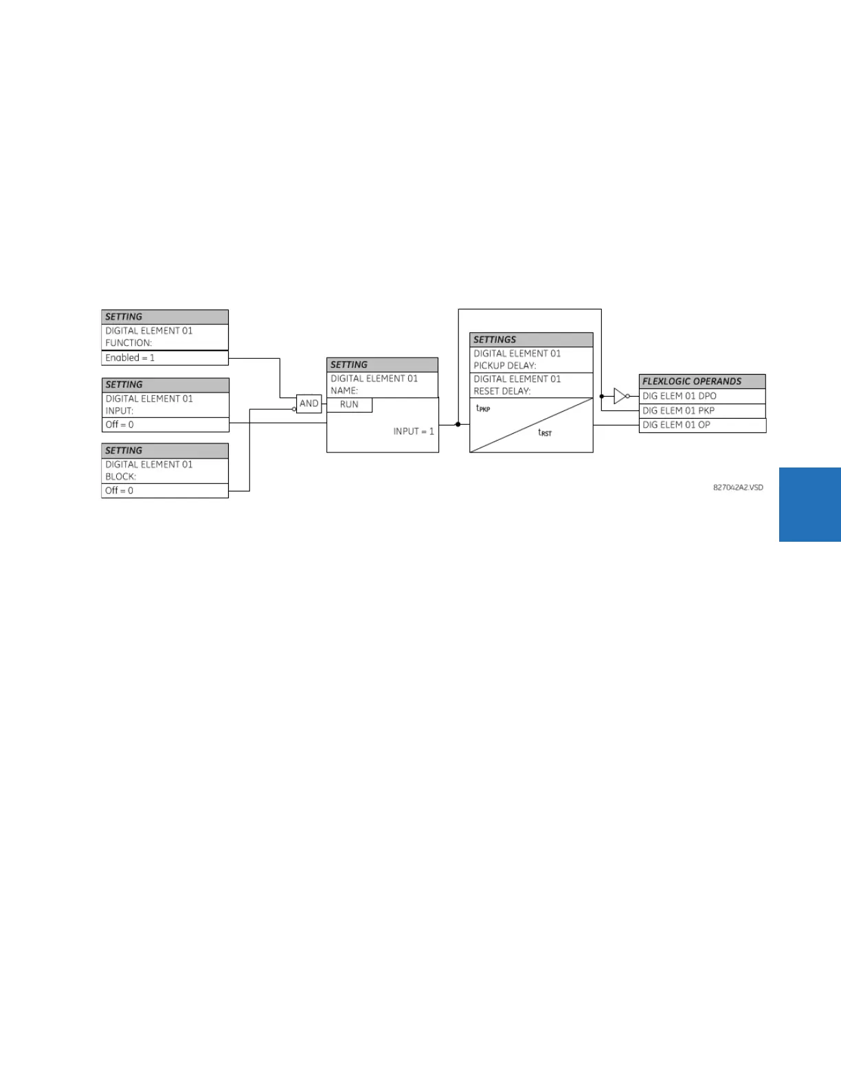
settings include a name to be referenced in any target message, a blocking input from any selected FlexLogic operand,
and a timer for pickup and reset delays for the output operand.
DIGITAL ELEMENT 1 INPUT — Selects a FlexLogic operand to be monitored by the digital element.
DIGITAL ELEMENT 1 PICKUP DELAY — Sets the required time delay from element pickup to element operation. If a pickup delay
is not required, set to "0," To avoid nuisance alarms, set the delay greater than the operating time of the breaker.
DIGITAL ELEMENT 1 RESET DELAY — Sets the time delay to reset. If a reset delay is not required, set to “0.”
DIGITAL ELEMENT 1 PICKUP LED — This setting enables or disabled the digital element pickup LED. When set to “Disabled,” the
operation of the pickup LED is blocked.
Figure 5-168: Digital element logic
Circuit monitoring applications
Some versions of the digital input modules include an active voltage monitor circuit connected across form-A contacts.
The voltage monitor circuit limits the trickle current through the output circuit (see technical specifications for form-A).
As long as the current through the voltage monitor is above a threshold (see technical specifications for form-A), the Cont
Op 1 VOn FlexLogic operand is set (for contact input 1—corresponding operands exist for each contact output). If the output
circuit has a high resistance or the DC current is interrupted, the trickle current drops below the threshold and the Cont Op 1
VOff FlexLogic operand is set. Consequently, the state of these operands can be used as indicators of the integrity of the
circuits in which form-A contacts are inserted.
Example 1: Breaker trip circuit integrity monitoring
In many applications it is desired to monitor the breaker trip circuit integrity so that problems can be detected before a trip
operation is required. The circuit is considered to be healthy when the voltage monitor connected across the trip output
contact detects a low level of current, well below the operating current of the breaker trip coil. If the circuit presents a high
resistance, the trickle current falls below the monitor threshold, and an alarm is declared.
In most breaker control circuits, the trip coil is connected in series with a breaker auxiliary contact that is open when the
breaker is open (see figure). To prevent unwanted alarms in this situation, the trip circuit monitoring logic must include the
breaker position.