CHAPTER 5: SETTINGS CONTROL ELEMENTS
M60 MOTOR PROTECTION SYSTEM – INSTRUCTION MANUAL 5-315
5
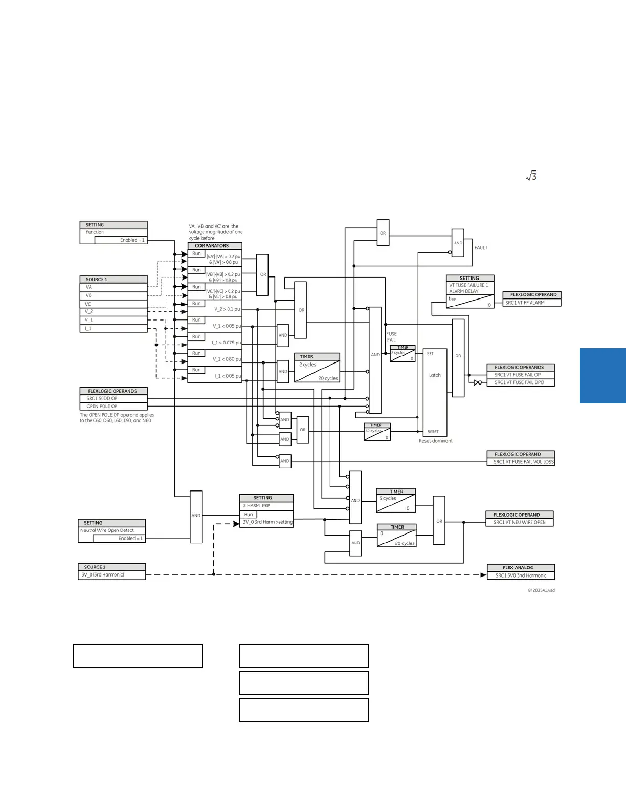
An additional condition is introduced to inhibit a fuse failure declaration when the monitored circuit is de-energized;
positive-sequence voltage and current are both below threshold levels.
VT FUSE FAILURE 1 FUNCTION — Enables and disables the fuse failure feature for Source 1 VT Fuse Fail.
NEUTRAL WIRE OPEN 1 DETECTION — Enables and disables the VT neutral wire open detection function. When the VT is
connected in Delta, do not enable this function because there is no neutral wire for Delta connected VT.
NEUTRAL WIRE OPEN 1 3 HRAM PKP — Specifies the pickup level of 3rd harmonic of 3V0 signal for the NEUTRAL WIRE OPEN
DETECTION
logic to pick up.
Base voltage for this element is
PHASE VT SECONDARY setting in the case of WYE VTs and (PHASE VT SECONDARY)/ in case
of DELTA VTs. The setting is found under
SETTINGS SYSTEM SETUP AC INPUTS VOLTAGE BANK PHASE VT SECONDARY.
Figure 5-179: VT fuse fail logic
5.8.11.7 Broken rotor bar detection
SETTINGS CONTROL ELEMENTS MONITORING ELEMENTS BROKEN ROTOR BAR
BROKEN ROTOR BAR
BROKEN ROTOR BAR
FUNCTION: Disabled
Range: Disabled, Enabled
START OF BRB
OFFSET: 0.40 Hz
Range: –12.00 to 11.99 Hz in steps of 0.01
END OF BRB
OFFSET: 2.00 Hz
Range: –11.99 to 12.00 Hz in steps of 0.01