CHAPTER 3: INSTALLATION WIRING
M60 MOTOR PROTECTION SYSTEM – INSTRUCTION MANUAL 3-15
3
CT connections for both ABC and ACB phase rotations are identical, as shown in the Typical Wiring Diagram.
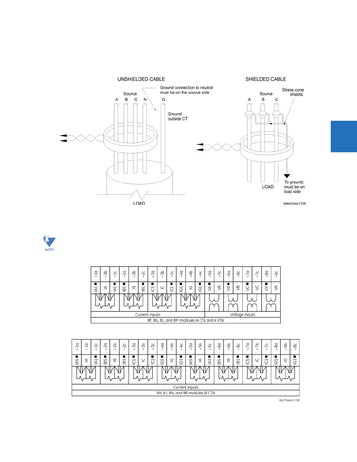
The exact placement of a zero-sequence core balance CT to detect ground fault current is shown as follows. Twisted-pair
cabling on the zero-sequence CT is recommended.
Figure 3-14: Zero-sequence core balance CT installation
The phase voltage channels are used for most metering and protection purposes. The auxiliary voltage channel is used as
input for the synchrocheck and volts-per-hertz features, which are optional features available for some UR models.
Figure 3-15: CT/VT module wiring
Substitute the tilde “~” symbol with the slot position of the module in the following figure.